[Kay Choe] can’t play the piano. Rather, he couldn’t, until he converted his keyboard to include LED-guided instruction. [Kay] is a microbial engineering graduate student, and the last thing a grad student can afford is private music lessons. With $70 in components and a cell phone, however, he may have found a temporary alternative.
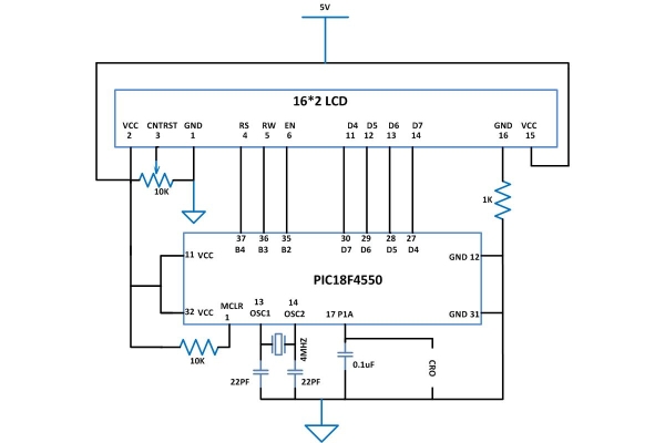
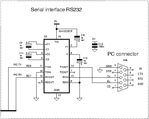
The build works like a slimmed-down, real-world Guitar Hero, lighting up each note in turn. We’ve seen a project like this before, with the LEDs mounted above the keys. [Kay]‘s design, however, is much easier to interpret. He embedded the LEDs directly into the keys, including ones above each black key to indicate the sharps/flats. An Android app takes a MIDI file of your choice and parses the data, sending the resulting bits into an IOIO board via USB OTG. A collection of shift registers then drives the LEDs.
 For a complete novice, [Kay] seems to benefit from these lights. We are unsure whether the LEDs give any indication of which note to anticipate, however, as it seems he is pressing the keys after each one lights up. Take a look at his video demonstration below and help us speculate as to what the red lights signify. If you’re an electronics savant who wants to make music without practicing a day in your life, we recommend that you check out [Vladimir’s] Robot Guitar.
Filed under: Android Hacks, led hacks, musical hacks 

September 22 2013
Hackaday Links: September 22, 2013
First we start with some protection… for your USB charged devices. Here’s a USB Condom which acts as a pass-through for the power rails but not the data lines. This prevents untrusted charger security exploits. [Thanks Markus]
[OutKastz] seems to think he’s uncovered a price matching conspiracy at Best Buy. His post references an HDTV video wall he has built. But he also discovered that there are two different version of the same television sold as the same SKU. His theory is that this prevents the big box from matching prices on half of their inventory.
When you’re in need of some breadboarding action with your Raspberry Pi and want to make it as painless as possible you need to build your own Pi Cobbler. This is the diy version of an Adafruit product, built using a couple of pin headers, stripboard, and an IDE cable.
Speaking of Adafruit, did you see Ladyada’s teardown of an ICEdot crash sensor?
[Phineas] is showing off a really really small hexacopter. Check out the maiden flight, as well as first indoor and first outdoor tests.
Perhaps this coded entry system will inspire a future project for you. It uses piezo elements to enter a code which unlocks the back door to the company. The glass door already had a series of large dots painted on it. This turns out to be a nice interface for a four button code system.
Many projects use a Raspberry Pi as a web server. But there is more than just one flavor available. [Jeremy Morgan] performed a variety of Pi server benchmarks using Nginx, Monkey, Lighttpd, and Apache. [Thanks Walter]
Can an old TV antenna reflector be used to boost the range of a WiFi dongle? We’re a bit skeptical. Let us know what you think in the comments.
And finally, we do wish there was more information on this upright piano used to play Doom [Thanks Itay].
Touch control for every key on the keyboard
Of all the musical instruments out there, the keyboard is among the worst for changing the pitch and timbre of individual notes. Wind and stringed instruments can do this easily in the hands of a skilled player, but outside the wheel and joystick controls of a few electronic keyboards, tickling the ivories means the only thing you can really change about how something sounds is the volume.
TouchKeys wants to put an end to this severe lack of dynamics available on keyboard instruments. Basically, it turns every single key on a keyboard into a multi-touch sensor, allowing any keyboardist to change the pitch, filter, timbre, or any other parameter of their instrument simply by moving their finger around on a key.
 TouchKeys works by overlaying all the keys on a keyboard with circuit boards that plug into a module hidden under the hood. These boards are studded with capacitive sensing points, allowing a computer to recognize where the player is touching each key, and modifying filters or volume for each key independently.
The TouchKeys Kickstarter is offering a kit to equip a 25-key keyboard with these sensors for about $550. A hefty price tag, but hopefully we’ll see this tech in real production keyboards in the future.
Camera-based touchscreen input via an FPGA
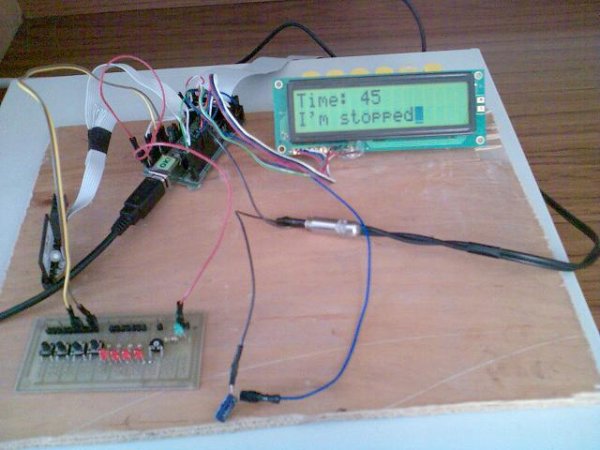
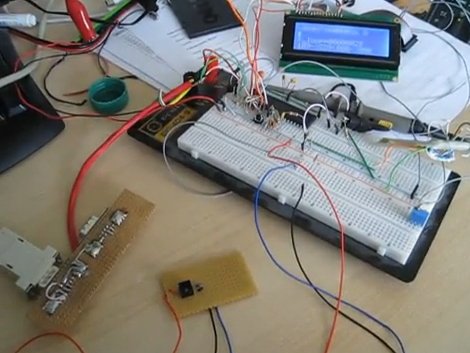
[Chonggang Li] wrote in to share a link to the final project he and [Ran Hu] built for their embedded systems class. It’s called Piano Hero and uses an FPGA to implement a camera-based touch screen system.
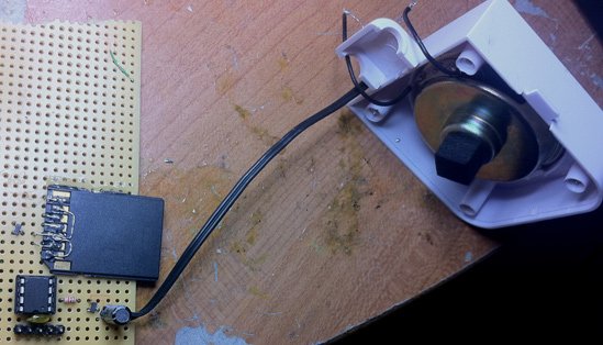
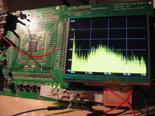
All of the hardware used in the project is shown above. The monitor acts as the keyboard, using an image produced by the FPGA board to mark the locations of each virtual key. It uses a regular VGA monitor so they needed to find some way to monitor touch inputs. The solution uses a camera mounted above the screen at an obtuse angle. That is to say, the screen is tilted back just a bit which allows the images on it to be seen by the camera. The FPGA board processes the incoming image, registering a key press when your finger passes between the monitor and the camera. This technique limits the input to just a single row of keys.
This should be much simpler than using a CCD scanner sensor, but that one can track two-dimensions of touch input.
The post LED-Guided Piano Instruction using pic microcontoller appeared first on PIC Microcontroller.