Quantcast
Channel: Sound - Audio Projects - PIC Microcontroller
Viewing all 110 articles
Browse latest View live

Shrieker using PIC16F676 Microcontroller

$
0
0

Recently a cell phone ring tone was in the news – it’s 17,000 Hertz and meant to be heard by teenagers, but
inaudible to adults.  Really got some people upset for some reason.  It got me wondering – what frequencies can I
hear?  I made the shrieker.  It can generate tones from 10,000 Hz to 22,000 Hz.

Shrieker

It’s a simple project.  The program doesn’t do much.
The button actual provides power to the PIC, so
pressing it starts the boot up.  Six pins read the inputs of
six switches.  This determines the frequency.  After that,
the PIC just generates a square wave of that frequency
on one of its pins that goes right to the speaker with a
capacitor to round the edges some.

The speaker was only rated to 7000 Hz, but seems to
work fine.

With all switches in the off position, the frequency is
10,000 Hz.  The switches function as binary inputs, most
significant digit on the right: 32, 16, 8, 4, 2, 1, so the
input can vary from 0 to 63.
frequency = 10,000 Hz + input*200 Hz
So the frequency range is 10kHz – 22.6kHz

The results?
My left ear can hear 14,600 Hz, my right 13,200 Hz.


For more detail: Shrieker using PIC16F676 Microcontroller

Current Project / Post can also be found using:

  • pic 12f675 sound
  • mp3 player code pic16f877a
  • pic 16f628 audio
  • how to connect ten different sounds with a microchip or speakers

The post Shrieker using PIC16F676 Microcontroller appeared first on PIC Microcontroller.


PIC MicroController Volume Adjuster Program(Proteus 8 Stimulation)

$
0
0

Hello everyone,
The important aspect of every learning is to induce curiosity and doing something meaningful to satisfy that.With the help of that curiosity, I’m here making a volume adjuster program which resembles the same in most devices but not that much, Here the default volume will be 10.Maximum volume will be 20 as well as the minimum volume will be 5.
PIC MicroController Volume Adjuster Program
Well, here I’m using Proteus 8 Professional for stimulation and Mikro C Pro Plus 2012 as Embedded Compiler for programming the microcontroller because I’ve already ran out of hardware and money :).

Step 1: Things You will need

Since this is a fully software stimulated program, You will need not more than the following softwares:

1.Proteus 8 (Any build or Version).
2.Mikro C (Any build or Version).

Step 2: The Connections.

Open Proteus. In the Component Mode, select Pick from devices and search and double click the following components:
1.LM016L (16×2 AlphaNumeric Display LCD)
2.PIC16F877A Microcontroller 
(Here i am going with 16F877A as it is the most common PIC Microcontroller)
3.A Resistor or POT(Value = 10k Ohms).
4. SW_ROT_3 switch

Here we’ll use the inbuilt crystal with the default frequency 8MHz.

I have used the SW_ROT_3 switch to avoid floating point errors.

I made a 4-bit connection to LCD as it is more than enough for this program.

Do the Following Connections:
1.Place the PIC16F877A
2.On the right side of it place the LCD Display.
3.In the LCD, connect VSS to gnd, VDD to +5V and RW , D0,D1,D2,D3 to ground(since its a 4 bit connection) . VEE is connected to +5V via a 10K ohms resistor.
4.We are going to use portB in PIC to control LCD. so, connect RB1,RB2,RB4,RB5,RB6,RB7 to RS,E,D4,D5,D6,D7 in the LCD respectively.

5.Connect the SW_ROT_3 switches as shown.


For more detail: PIC MicroController Volume Adjuster Program(Proteus 8 Stimulation)

The post PIC MicroController Volume Adjuster Program(Proteus 8 Stimulation) appeared first on PIC Microcontroller.

Build a musical EKG with the Freescale FRDM-KL05

$
0
0

Short Introduction:

I have been following the Battle of the DreamBoards Championship with interest and I enjoyed the variation of functionality features put together in each of the dreamboards.  I especially had my attention attracted by the combination of audio inputs and outputs, analog to digital and digital to analog converters, and the microcontroller digital processing of signals that I saw in PC64, which was also the winning dreamboard.  This combination of features inspired me to build one of the old ideas that has been waiting “dormant” somewhere in my mind for a while.  Here is a description of my project:

Why I built this project:

Electrocardiographs (ECG) measure electric signals generated by the heart and display them in a graphical format on a screen or on a hard copy electrocardiogram.  Most of the times when I go to a doctor for check-up I have one of these electrocardiograms measured on my heart.  More extensive monitoring of the heart activities uses 24 hours ECG or even two weeks ECG.  The recorded data is then processed in medical offices to determine if there was any ECG waveform aberration.  So in my case once in a while I may have an irregular heart beat or a premature ventricular contraction (PVC) which typically happen in normal heart activity but if there are too many then they need medical attention.Build a musical EKG with the Freescale FRDM KL05

What am I trying to do:

ECG measurement and analysis is a powerful tool for detecting problems with the heart activity when it is recorded, but how about the rest of the time?  Can I have a device that continuously monitors the heart activity every day through ECG measurements?   The technology is available and ECG heart monitors are inexpensive, but the problem I see is how I can actually use them to continuously monitor my heart activity?  For how long I can keep my eyes on the screen and watch the ECG waveform in real time?  I also need to do other things during the day so I am not able to continuously watch that screen.  If I record the ECG data for a period of time I will then need to go and analyze it, which takes time and thus I find inconvenient.

I kept thinking about how I could monitor my heart activity without disturbing my normal activities.  So I decided to build an ECG device that can be attached to an audio system and when it detects aberrations in ECG waveform it distorts the music or voice that plays through the audio system (CD player, radio, TV, or any appliance that outputs an audio signal).  This way I can monitor my heart activity while doing my regular daily activities without spending specific time to watch or analyze he recorded the ECG waveforms.

How does it work:

The ECG unit continuously measures the ECG and when it detects an aberration in heart activity it sends a command to the audio unit which then either increases the pitch of the music or voice played by the speaker.

How I implemented it:

I have chosen to implement this project on a Freescale FRDM-KL05Z development kit that has a MKL05Z32VFM4 microcontroller This is a very inexpensive microcontroller and development kit that can operate up to 48MHz has 32kB of flash non volatile memory various analog and digital peripherals and what I planned to use in my application it has a 12-bit analog-to-digital converter This development kit supports the open standard embedded serial and debug adapter OpenSDA What I also liked on this  FRDM-KL05Z development kit was that it has Arduino type GPIO headers that allows me to easily connect Arduino type shield modules Thus I could use a shield module for the front end ECG analog path

Here is a picture of the Freescale  FRDM-KL05Z development kit

Setting up the design environment for the Freescale  FRDM-KL05Z board

The first step after I received the   board was to setup the design environment In this process I found very useful a quick start guide file  FRDM-KL05Z Quick Start Guide(Rev 1.1 available to download on the Freescale website part of a quick start package with precompiled examples and OpenSDA applications

This document has guided me step by step through installing the required drivers, the OpenSDA programming and debug environment, and loading and running an application. I found quite convenient the MSD flash programmer where I only need to drag and drop the file and it gets automatically programmed into the microcontroller.

After getting the  FRDM-KL05Z board up and running I installed Keil micro vision(uvision programming environment This tool provides source code editing and program debugging so I have chosen to use this platform for the rest of my work on this project

I also want to mention that during this setup process I bumped into various issues for which I either found solutions on Freescale support webpage or I got help from Freescale support team.  I was impressed on how fast the support engineers responded to my requests, like for example I sent a request on July 6 at 9PM and a support representative responded to me in 5 hours, at 2AM.  I also contacted the support team on a Saturday with a design question about configuring GPIO pins, and I was surprised to get an answer during that weekend on Sunday; I thought I will need to wait until the week starts, but the response came during that weekend.

The Electrocardiogram Circuit:

For the front end analog amplification of heart electrical signals I chose to use an Olimex Shield-EKG/EMG module from Newark store.

This ECG shield works with multiple types of electrodes, and I chose this set, also from Newark store, that attaches to the shield module through a connector:

The ECG shield board connectors plug directly into the headers that I soldered on the Freescale  FRDM-KL05Z board

Before I describe the rest of the components of this project I would like to show a block diagram.

Block Diagram of the Entire System

This system has three main parts ECG front end module  FRDM-KL05Z data processing and an audio processing module

The ECG shield module measures continuously the ECG waveform which is then sampled by the analog to digital converter inside the   development kit The sampled values are processed to extract the peak R-waves and store the samples of a R-wave to R-wave cycle which represent the time between two consecutive heart beats These samples become the expected values for the following cycle So in each R-wave triggered cycle the  FRDM-KL05Z code compares the real time measured ECG samples with the expected values and if it finds discrepancies it generates specific flags When a flag is detected the code generates control signals that are sent to the audio processing module to either increase or decrease the pitch of the audio signal that passes through the module For example if the person monitored by this system listens to music on the radio CD or mp3 player the music will change the pitch higher or lower depending on what aberration has been detected on the ECG waveform Similar sound pitch changes happen if the person watches a show on the TV or DVD player This way the heart activity is monitored while doing other activities without the need to spend dedicated time for this monitoringBuild a musical EKG with the Freescale FRDM KL05 schematic

Schematic of the System

The main unit is the   evaluation kit which provides power to the ECG shield and provides the control signals to the audio processing board The ECG shield amplifies and filters the electrode signals and then sends the output to PTB13 GPIO port of the  MKL05Z32VFM4 microcontroller on the  FRDM-KL05Z board This microcontroller analyzes the analog ECG waveform and when it detects heart activity problems it sends two digital pulse signals to the audio processing module one that increases the pitch and one that decreases it The microcontroller also controls four LEDs that display what was wrong with the ECG waveform that generated a flag The four ECG aberrations signaled are LED1 Early R-wave peak(Irregular heart rate too short LED2 late R-wave(Irregular heart rate too long LED3=P-wave and/or T-wave magnitude too large LED4=P-wave and/or T-wave magnitude too small

The audio processing module is a voice changer kit available to purchase from various places, like for example on amazon.com:

http://www.amazon.com/Velleman-MK171-Voice-Changer/dp/B004XZQ6RE/ref=sr_1_13?ie=UTF8&qid=1440257874&sr=8-13&keywords=voice+changer

Here is a picture of my audio processing board:

I have modified this kit by adding an audio line-in and an audio line-out connectors instead of soldering a microphone and a speaker to the board.

In order to control this kit with TTL pulses instead of pressing the buttons I had to solder two wires on the high pitch and low pitch switches and one on the ground These signals are normally pulled-up and they need to be driven low to get the same effect as pressing the buttons but because   board operates at 3.3V and the voice changer kit at 5V I couldn’t connect directly these wires to the   outputs To solve this issue without adding level shifters I inserted a diode in series with the wire The diode allows pulling down the node but blocks the 5V coming into  FRDM-KL05Z when the signal is not asserted

Developing the Code

I started from two example codes and I expanded them into the complete code.  One of the example code was LED_Blink that comes in the KL05-SC package that I downloaded from Freescale website.  There is a guide document in this package that describes how to install and run the code examples, FRDM_KL05ZSCG_KEIL_rev1, which I found very informative and easy to follow.  This one is specific for Keil tools, and there are two other similar documents for IAR and Code Warrior tools.

So I used the LED_Blink to learn how to generate and send digital signals to output ports, which I needed for controlling the audio processing module.

The other example code that I used was AdcDemoWithDMA This code configures calibrates and performs analog-to-digital conversions using the 12-bit ADC inside the  MKL05Z32VFM4 microcontroller I found this example code very useful for implementing my ECG signal sampling function and I decided to actually start form this example code and build the rest of the project on top of it


For more detail: Build a musical EKG with the Freescale FRDM-KL05

Current Project / Post can also be found using:

  • sound library with microcontroller

The post Build a musical EKG with the Freescale FRDM-KL05 appeared first on PIC Microcontroller.

Audio CRO using PIC12F675 Microcontroller

$
0
0

This project is a miniature Audio CRO. For those not familiar with the abbreviation “CRO,” it means “Cathode Ray Oscilloscope” and this is sometimes shortened to “SCOPE or O-Scope.”

A “CRO” is a piece of test equipment with a screen. It produces a visual indication of a waveform, via a probe, when the waveform is connected to the input terminal of the CRO.
If you connect a microphone to the probe and whistle into the mic, the CRO will produce a picture (trace) of the waveform. It will be in the shape of a sinewave. The screen is very similar to an old-style TV set (called a “picture-tube”) and the picture is created by firing a beam of electrons from the back of the tube (called the “neck'”) to the front of the tube where a layer of phosphorescent material glows when the beam hits it.

Audio CRO
The beam of electrons is diverted from left to right via an electromagnetic field or an electrostatic field and this produces a line across the screen.
The beam is then deflected up or down by magnetic or electrostatic fields at 90° and this enables it to produce all sorts of patterns.

Here are some photos of the prototype Audio CRO. Note the use of surface-mount components allows a lot of parts to be placed in a very small space.
The 10mH inductor has been placed at an angle to make it less sensitive to the motor magnets so that it only picks up the field of the super-magnet placed on the end of the motor.
The motor is actually a 12v motor from the eject mechanism of a CD player. It operates down to 3v and the RPM at 3v is very low. That’s why it was chosen.
There are a lot of technical challenges to overcome when electronics is combined with mechanical devices. You will experience these when you build the project.  

This is exactly what we have done in this project. But in an extremely miniaturised way.
Our screen is digital. It is rotating to produce a screen of light made up of “pixels.”  We have an upright strip of LEDs and this is spun from left to right to create a screen that is 8 pixels high.
As you can see from the photos, the project is built on a small PC board containing the PIC chip, components to interface a pick-up coil and microphone to the chip and 4 cells. 16 LEDs are soldered to the edge of the board to create the “display.” The PC board is soldered to the shaft of a motor and a separate 3v supply is used to rotate the motor. We have used electro-magnetic detection to detect the starting point for each rotation of the display so that the RPM of the motor is not important. The display will remain absolutely steady, not matter how fast the shaft is rotated.
However the length of the display will contract if the motor is slowed down.
We then turn each LED on and off many times during the visual part of its rotation, making a screen resolution of  up to 8 x 60. (But the audio section has a screen size 8 x 48). This might seem a small area but the project is a CONCEPT DESIGN.

CONCEPT DESIGN
It is designed to show the capabilities of one of the smallest and simplest chips in the PIC microcontroller range. It’s to “get you started” and if it were a complex project, it would be by-passed by those who we are aiming at – the BEGINNER.
Even at this basic level there are a number of features to challenge the brightest hobbyist – so be prepared for a really absorbing project.

LED  MYTH
There is a generally accepted thought that the voltage across a LED is a fairly constant value. But this is not so.
As the current across it drops, the “characteristic voltage drop” also drops significantly.
For the LEDs used in this project, the voltage drops from 2.3v (when full current is flowing) to 1.66v when less than 1mA flows.
This value is important as we are placing 4 LEDs across a 5.4v supply and we need to know if any current will flow through the combination when the project is resting.
In our case, 4 LEDs at rest requires 6.64v   This means no current will flow when the supply is 5.4v (it has to be higher than 5,4v for the LEDs to start to conduct).
This is the main reason why we have had to place two LEDs in series on each output. If we had only 2 LEDs from the positive rail to 0v rail, (with the output of the chip connected to the mid-point) they would illuminate when the drive-line was in “input-mode (high-impedance mode).”

THE DISPLAY
The display is made from 16 LEDs. The LEDs are in pairs and this makes 8 “pixels.”  Two LEDs are connected from an output to the positive rail and two LEDs to the negative rail.
When a control line is HIGH, two LEDs are illuminated and when it is LOW, the other two are illuminated. When the control line is an input, none are illuminated.
Both pairs of LEDs cannot be illuminated at the same time.
To make the display appear steady, the LEDs must be turned on at exactly the same instant, during each revolution. This is called REGISTRATION and is done by sensing the magnetic flux from a magnet and relying on the voltage produced by an amplifying transistor to be detected as a HIGH by GP3, the input-only line.
We have one further problem with displaying an audio waveform.
We need to SYNCHRONISE the rotation of the display with the audio. With a CRO, this is done via a feature called “triggering.”
The beam is held at the left side of the screen until the signal reaches a certain value and this makes every waveform (called a trace) retrace the previous to produce a steady picture.
Since we cannot synchronise the audio with the rotation of the display, we have used a clever feature called SAMPLE AND HOLD.
We sample the audio to produce 48 “points” and store these in registers 30h to 5Fh.
The program then waits for the start of the next revolution and displays these 48 points. It then waits for the start of the next revolution and displays the points again. It does this 30 times and takes another sample of the audio. This produces about 2 updates every second.
The result is a very steady picture.
So, there you have it. A sample-and-hold audio CRO.


For more detail: Audio CRO using PIC12F675 Microcontroller

Current Project / Post can also be found using:

  • how to generate speech from PIC microcontroller
  • microcontroller based audio amplifier project

The post Audio CRO using PIC12F675 Microcontroller appeared first on PIC Microcontroller.

Circuit design and electronics using pic-microcontroller

$
0
0

I completed a 2-part assignment for this week. The first part was to build a sorta-random sound generator based on a schematic that Joe Paradiso made available. The second part was to build a circuit that could transmit MIDI messages – this will go towards my final project.

Sound generator

The description for this assignment is here.
Electronics knowledge base from 2001 can be found here.

Circuit design and electronics

Midi Output

Midi output (and probably input) is going to be important to my final project. For this reason I’ve decided that one important step between now and completing my final project is to learn how to emit (and receive) MIDI messages from a PIC. I’ve found several resources online that give directions on how this can be done. Here are several of the more useful ones:

MIDI is basically serial data transmitted at 31,250 baud (bits-per-second) through a circuit with a resistance of about 660 ohms. Parity must be set to NONE, the number of stop bits must be set to 1 and finally the number of data-bits must be set to 8. The baud rate MIDI uses means that during transmission each bit should last for 32 micro-seconds. MIDI is transmitted in chunks of 3 bytes (each byte is 8 bits) and each transmitted byte is padded with a start bit (0) before it and a stop bit (1) after it. The three bytes of the typical MIDI message consist of one status byte and 2 data bytes (in that order). There is a lot of information online about what makes up valid status/data bytes. The bits in each byte are transmitted Least-Significant-Byte (LSB) first.

So if I wanted to transmit the number 144 (this is the code for a NOTE-ON in MIDI), the bit-pattern would be:

what I want to tranmit: 10010000
what bits get put on the line (read left-to-right): 0 00001001 1
(note: the spaces are just to show that there is a start and stop bit)

I was doing some testing while I developed my circuit, and I was sending the following bytes down the MIDI line: 144 144 144

Circuit design and electronics

This sequence caused me a lot of headache, because I didn’t realize for the longest time that IT’S NOT VALID MIDI. It’s three control bytes in a row and no data bytes. So even when I had the hardward constructed correctly, the computer was still not registering any MIDI messages coming through. Be careful of that.

Read my notes from this testing session here (note that in Hexidecimal format, 144 is 0x90)

Since MIDI is really just serial data, it’s pretty easy (in theory) to transmit it, since many microcontroller development languages have routines for transmitting and receiving serial built-in. The signaling in MIDI is based on current rather than voltage though, which means that in order to transmit a message, you have to have a certain amount of current flowing through the circuit. For longer MIDI cables, you’ll need more current pushing through the circuit.

Resting state on the line is when no current is flowing. This is actually a logical 1. So I think about it like this:

  • Want to transmit a 1 -> no current flows
  • Want to transmit a 0 -> flow that current!


For more detail: Circuit design and electronics

The post Circuit design and electronics using pic-microcontroller appeared first on PIC Microcontroller.

Circuit design and electronics using pic-microcontroller

$
0
0

I completed a 2-part assignment for this week. The first part was to build a sorta-random sound generator based on a schematic that Joe Paradiso made available. The second part was to build a circuit that could transmit MIDI messages – this will go towards my final project.

Circuit design and electronics

Sound generator

The description for this assignment is here.
Electronics knowledge base from 2001 can be found here.

PDF of the circuit diagram
Video with sound of my board in action! (use quicktime to view)

Midi Output

Midi output (and probably input) is going to be important to my final project. For this reason I’ve decided that one important step between now and completing my final project is to learn how to emit (and receive) MIDI messages from a PIC. I’ve found several resources online that give directions on how this can be done. Here are several of the more useful ones:

MIDI is basically serial data transmitted at 31,250 baud (bits-per-second) through a circuit with a resistance of about 660 ohms. Parity must be set to NONE, the number of stop bits must be set to 1 and finally the number of data-bits must be set to 8. The baud rate MIDI uses means that during transmission each bit should last for 32 micro-seconds. MIDI is transmitted in chunks of 3 bytes (each byte is 8 bits) and each transmitted byte is padded with a start bit (0) before it and a stop bit (1) after it. The three bytes of the typical MIDI message consist of one status byte and 2 data bytes (in that order). There is a lot of information online about what makes up valid status/data bytes. The bits in each byte are transmitted Least-Significant-Byte (LSB) first.

So if I wanted to transmit the number 144 (this is the code for a NOTE-ON in MIDI), the bit-pattern would be:

what I want to tranmit: 10010000
what bits get put on the line (read left-to-right): 0 00001001 1
(note: the spaces are just to show that there is a start and stop bit)

I was doing some testing while I developed my circuit, and I was sending the following bytes down the MIDI line: 144 144 144

This sequence caused me a lot of headache, because I didn’t realize for the longest time that IT’S NOT VALID MIDI. It’s three control bytes in a row and no data bytes. So even when I had the hardward constructed correctly, the computer was still not registering any MIDI messages coming through. Be careful of that.

Read my notes from this testing session here (note that in Hexidecimal format, 144 is 0x90)

Circuit design and electronics

Since MIDI is really just serial data, it’s pretty easy (in theory) to transmit it, since many microcontroller development languages have routines for transmitting and receiving serial built-in. The signaling in MIDI is based on current rather than voltage though, which means that in order to transmit a message, you have to have a certain amount of current flowing through the circuit. For longer MIDI cables, you’ll need more current pushing through the circuit.

Resting state on the line is when no current is flowing. This is actually a logical 1. So I think about it like this:

  • Want to transmit a 1 -> no current flows
  • Want to transmit a 0 -> flow that current!


For more detail: Circuit design and electronics

Current Project / Post can also be found using:

  • CRO using PIC micro
  • how to play sound file by pic controller
  • interfacing of pic with soundsensor
  • sound sensor digital output to pic16f877a

The post Circuit design and electronics using pic-microcontroller appeared first on PIC Microcontroller.

One-chip sound player.

$
0
0

The purpose of this project was to create a sound player that can play high quality sound using nothing but a single chip (plus an SD card for data storage).

The chosen microcontroller was the PIC12F1840. It was chosen because of its fast clock rate (up to 32 MHz). Since microchip PICs have this atrocious property of executing one instruction every four clock cycles, this results in 8MIPS performance.

One-chip sound player.The second reason for the choice was the hardware SPI module – bit-banging SPI is not hard, BUT doing it fast enough to sustain the sound playback would be – the hardware SPI module helps by allowing the SPI clock to be as high at 8MHz without using nearly as much CPU time as bit-banging would. The reset of the circuit design was easy: the PIC outputs a PWM waveform to drive the speaker, which is amplified by a MOSFET, PIC’s SPI controller talks to the SD card, and another GPIO is used to provide power to te SD card allowing it to be powered off and thus letting the circuit sleep in very low power mode (nanowatts of power used). The pic is overclocked using the OSCTUNE register to 33MHz from the stock speed of 32MHz.

The SD card driver is my own work, and supports SD/MMC/SDHC/RS-MMC/HS-MMC/miniSD/microSD/transFlash and whatever others are in that family. Card is initialized at 375KHz (which is within spec), and then the bus is clocked at 8MHz for data reads/writes. The driver is peculiar for a few reasons, mainly because it does not try to be an abstraction between the SPI bus and the caller, thus the driver will init the card, and set it up to stream sectors to the caller. The caller then calls spiByte() directly to read sector data. Every 512 calls, a call to sdNextSector() is needed to notify the SD driver that we want the next sector & properly wait for it to start.

Since there is some time between the end of streaming of one sector and beginning of streaming the other, buffering is used for audio data. The buffer is a simple circular buffer that the audio thread reads from, and the SD thread writes to. When buffer is full, SD thread busy-waits for a slot to open to write data into. Since SD cards do not care how much time passes between clock ticks, this wait can be as long as needed.

One-chip sound player.

The filesystem driver (uFAT) is also my own work, and is a tiny tiny FAT16 implementation. It supports only: short filenames, only FAT16, only read, only root directory. It can: enumerate files’ names/sizes/flags and return the set of sector extents a file occupies. A sector extent is defined as a contiguous range of sectors (a “fragment” in FAT terms). The caller then reads those sectors by itself (allowing the caller to thus avoid the needless layer of abstraction and thus time waste).


For more detail: One-chip sound player.

Current Project / Post can also be found using:

  • AUDIO DESIGN WITH PIC18 MICROCONTROLLER
  • microcontroller programming for speaker
  • pic generate tone

The post One-chip sound player. appeared first on PIC Microcontroller.

Echo Mp3 DIY Audio player using PIC18F46K20

$
0
0

The EchoMp3 is a small DIY* Audio player.

  • Mp3, Wav, Ogg-Vorbis, Wma and Mid formats are supported.
  • 4, 8, 16 GB SDHC cards used as storage.
  • FAT (FAT16) and FAT32 supported.
  • Low power operation with two AA (HR6) 1V2 Ni-Mh batteries.
  • Power input range is +2.4V … +3.0V
  • Runs on a PIC18F46K20 at 64 MhZ.
  • Up to 320 kBps bitrate CBR  and VBR at 44,1 kHz supported.
  • ID3 v2.3 tags supported.
  • Full user control (volume, track, pause, skip, directory) with a 5-way micro joystick.
  • Optional OLED Module 1 with RGB OLED 96×64 pixels.
  • Real time display of bitrate, sampling rate, elapsed time, songnumber, …
  • Directory scrolling and file fragmentation support. Directory depth up to 10 accepted.
  • SDHC (High Capacity) Cards now standard. Here are some compatible cards.
  • Serial interface control so the player may be used as a playback module.
  • High quality stereo DAC with a S/N ratio of typ. 94dB.
  • THD of max.  0.07%
  • Sounds way much better than an iPod or Smartphone!
  • Voice Recording in OGG Vorbis-format will be added later.


* Do It Yourself.

 Schematic & pcb (Eagle 4.11e), hex file available. Player Software Updated on February 12, 2011.

Circuit explanation / Getting started:

 Echo Mp3

PIC18F46k20 The 18F46k20 offers high speed and low power operation. Well suited for a portable application such as this one.
VS1053 MP3 decoder chip. Enhanced performance compared to the VS1001Kand VS1002 Sounds great! Future enhancements (equalizer and so on) are possible. Thanks to GBUF, no need for large capacitors at the earphone outputs. The chip also has a recording mode!
SDHC Royalty-free and open source protocol makes this a great memory to work with. Finding a socket was more difficult. Format the card as FAT (FAT16) or FAT32, then copy them (all at once) to the card (with a cardreader.) Directories may be used. Tagging of your MP3 files can be done with Mp3 tag tools (freeware) and Audio Tags Editor (evaluation period.)
OLED OLED Module 1 with 96×64 pixels RGB OLED, Size: 0.95″Needs a +14V Vdd, this is generated by a TPS61080
Controls With the micro joystick, there are 8 user controls available. Two for volume (up & down) , track (left & right) , pause/play (short enter), skip (long enter) and directory scrolling (short enter to go into pause, then up/down to scroll,  enter to go to the selected directory.) Serial interface: volume (+ & ) , track (b & n) , hold/play (h & p), repeat one/play all (r & a), continuous/single play (c & s), goto tracknumber (ex: 14<ENTER> )

Volume, repeat and continuous settings are stored and reloaded on reboot.

Power The MCP1640 DC-DC step-up converter makes it possible to power the whole circuit from only one AA battery. Some larger SDHC cards will not boot with a weak battery though. We have chosen two AA batteries for enhanced stability and endurance. Power input range is +2.4V … +3.0V Do not exceed this!
PCB: We used as much SMD-parts as possible. The PCB from our shop is a double sided and 100% connection tested PCB with plated-through-hole connections. All holes are drilled already. PCB size = 66,50 x 54.90 mm


Schematics: (eagle-files and library can be downloaded below.)

Full resolution image: schematic and pcb (GIF format) Right-click and save as, then open in an image viewer (sch is too large for some browsers.)

Bill of Materials (Parts List)

Important note: The following sections from the schematic are not needed in this particular setup, and are left out on assembly: EE_PROG, USB, RDS TUNER, ACCELERATOR

For more detail: Echo Mp3 DIY Audio player using PIC18F46K20

Current Project / Post can also be found using:

  • dound pic
  • tones generator with Pic12f675

The post Echo Mp3 DIY Audio player using PIC18F46K20 appeared first on PIC Microcontroller.


MIDI-Controlled Analog Music Synthesizer

$
0
0

For my electrical engineering senior design project, I decided on designing a analog music synthesizer with MIDI control. I have to admit, this was what I wanted to do since high school and was my ultimate goal as a musician, artist, DIY person, and engineer. This project, in the end, will combine all of my knowledge into one nice little package that I get to show off to friends, family, and faculty and is to be completed by the end of this year.MIDI-Controlled Analog Music Synthesizer

The first image is the Alesis Q25 MIDI keyboard I purchased to test with.

The second, third, and fourth images are of one of the initial synth implementations.

The initial design features two voltage-controlled pulse oscillators (VCOs) scaled at one volt per octave. MIDI control is done with a PIC microcontroller that receives data and outputs it to a digital to analog converter (DAC). The voltage from the DAC is used as a control voltage (CV) for the oscillators. Velocity has not been implemented in this version and the last note played is always heard at output.

The fifth image is our current revision. It features the addition of a voltage-controlled amplifier (VCA). With this version, we now have a MIDI-controlled monophonic synthesizer. It is not in the video.

I’ll add another video of the most recent revision as soon as I get back into the lab.MIDI-Controlled Analog Music Synthesizer schematich

Tuning is an issue in the upper octaves, as demonstrated in the video, but will be fixed soon. The video demonstrates the operation of the one volt per octave scaling and MIDI control with the keyboard. Please post any comments about my project or ideas of what should be added in future revisions. Thanks! 😀

Update (8.25.2015)

Sorry everyone, I never got around to documenting


For more detail: MIDI-Controlled Analog Music Synthesizer

The post MIDI-Controlled Analog Music Synthesizer appeared first on PIC Microcontroller.

MIDI-Controlled Analog Music Synthesizer

$
0
0

For my electrical engineering senior design project, I decided on designing a analog music synthesizer with MIDI control. I have to admit, this was what I wanted to do since high school and was my ultimate goal as a musician, artist, DIY person, and engineer. MIDI-Controlled Analog Music SynthesizerThis project, in the end, will combine all of my knowledge into one nice little package that I get to show off to friends, family, and faculty and is to be completed by the end of this year.

The first image is the Alesis Q25 MIDI keyboard I purchased to test with.

The second, third, and fourth images are of one of the initial synth implementations.

The initial design features two voltage-controlled pulse oscillators (VCOs) scaled at one volt per octave. MIDI control is done with a PIC microcontroller that receives data and outputs it to a digital to analog converter (DAC). The voltage from the DAC is used as a control voltage (CV) for the oscillators. Velocity has not been implemented in this version and the last note played is always heard at output.

The fifth image is our current revision. It features the addition of a voltage-controlled amplifier (VCA). With this version, we now have a MIDI-controlled monophonic synthesizer. It is not in the video.

I’ll add another video of the most recent revision as soon as I get back into the lab.MIDI-Controlled Analog Music Synthesizer schematich

Tuning is an issue in the upper octaves, as demonstrated in the video, but will be fixed soon. The video demonstrates the operation of the one volt per octave scaling and MIDI control with the keyboard. Please post any comments about my project or ideas of what should be added in future revisions. Thanks! 😀

Update (8.25.2015)

Sorry everyone, I never got around to documenting


For more detail:  MIDI-Controlled Analog Music Synthesizer

Current Project / Post can also be found using:

  • generating sound in pic mcu by pwm

The post MIDI-Controlled Analog Music Synthesizer appeared first on PIC Microcontroller.

Alchemist Forseti APD15A RC Integrated amplifier

$
0
0

We recently had a customer present this faulty Alchemist Forseti integrated amp for repair – I’d guess this dates from the 1990’s and has been well looked after. It’s a bit of a bruiser as you can see from the extensive heatsinking!Alchemist Forseti APD15A RC Integrated amplifier

Unfortunately it developed a DC fault on the loudspeaker outputs and destroyed the customers speakers, so it’s now in the naughty corner awaiting surgery.

Access to the internal circuitry is via the top panel, which is secured by 13 cap head screws.

There are 13 screws to remove in total, an allen key is needed.

The rear panel has good connectivity for analogue sources (all line level, no phono input  but there are two pre-outputs to drive extra power amps should you need even more power.

Once the top panel is removed, this is the view of the printed circuit boards and power supplies – it’s very nicely laid out.

The Forseti is constructed as a dual mono design, which should give better channel separation and therefore improved stereo image – here is one channel’s output stage which employs two pairs of output transistors per channel – 2SA1302 are the PNP transistors and 2SC3281 are the NPN making a class B push pull output stage.

Each amplifier channel is fed power from it’s own dedicated power supply comprising 200VA toroidal mains transformer, bridge rectifier and four 10000uF/ 50V resevoir capacitors.Alchemist Forseti APD15A RC Integrated amplifier schematich

All of the the inputs are electronically switched by relay to keep signal paths extremely short for best possible sound quality.

The Forseti is a very well constructed amplifier which promises excellent performance – we will have to wait to hear this until we have diagosed and fixed any issues.


For more detail: Alchemist Forseti APD15A RC Integrated amplifier

The post Alchemist Forseti APD15A RC Integrated amplifier appeared first on PIC Microcontroller.

eDrum – Trigger MIDI Converter using PIC16F877

$
0
0

Introduction

This page is about electronic drums. Here you will find detailed information on how to build an electronic Trigger to MIDI Converter module, based on PIC Microcontroller, and how to build the triggers. This project has been developed for many years now, and it is constantly improving. You can expect professional results form your eDrum module. Let’s start with the…

MIDI Converter

Design description

eDrum design is based on PIC16F877 RISC microcontroller from Microchip running at 20MHz, two line (16×2) LCD with backlight, and some operational amplifiers. It has 22 analog inputs, 2 digital inputs, 22 input gain potentiometers, 4 control buttons, one MIDI out and one serial RS-232 out.

The goal for this design was to use easy to find and cheap electronic components, while maintaining results at the professional levels. I also wanted the design to be modular and easily expandable. This has been achieved by using PIC microcontroller and carefully designed firmware, written in assembly language.

It was not my intention to design an instrument that already exist and is relatively cheap, like Alesis DM4 or DM5. Instead, my idea was to take advantage of equipment we already own (computer with soundcard, synth, sampler,…) to produce the drum sound. So, all that is needed is… Trigger-to-MIDI conversion. Because of that, eDrum will not offer any drumkits or sounds.

Result

I’ve been working on a professional rackmount version of eDrum. This is the latest unit, “ED248”:


For more detail: eDrum – Trigger MIDI Converter using PIC16F877

The post eDrum – Trigger MIDI Converter using PIC16F877 appeared first on PIC Microcontroller.

How to set up your B&W Zeppelin Air

$
0
0

With the B&W Zeppelin Air being such a popular iPod docking station as well as a fantastic AirPlay compatible device we thought it would be a good idea to write a ‘how to’ on setting up your new Zeppelin Air.How to set up your B&W Zeppelin Air

As of September 2012 newer machines are installed with a slightly newer firmware version. The main reason for this is to make the Zeppelin Air easier to setup for AirPlay. The main benefit being you can now get AirPlay setup wirelessly rather than having to connect an Ethernet cable from your Zeppelin Air and your PC.

Apple’s AirPlay technology allows music to be streamed wirelessly from your Mac or PC to your Zeppelin Air. You can also bypass the computer entirely if you want and stream high-quality audio directly from your iPhone, iPad or iPod touch.

B&W have released a new app to walk you through the setup of this feature so no need to flick through manuals finding the right step or messing around with cables. The app will show you pictures of each step throughout the setup. If you want to make use of the AirPlay feature and don’t currently own an iPod or iPad etc. in the near future B&W will be releasing a program for your PC or Mac very similar to the current one for iPods.

The app is called ‘Bowers & Wilkins AirPlay Setup’ and is available free on the App Store. Once you have downloaded the app all you have to do is start it up and do the following:

Once the app has started up you will see the following screen,

As you can see from the welcome page of the app you can set up as many Bowers & Wilkins Wireless Music Systems as you like. For each system you want to setup just click ‘add new’.

So for setting up your Zeppelin Air you need to click the ‘add new’ button on the bottom right.

You will then be shown a message to make sure you have removed any docked or connected devices and once you have done this power up the system.

The first thing you should see on your Zeppelin Air is the led flashing red.

It will flash red for a few moments then start flashing yellow, this means it is ready to be setup.

Once you see the yellow LED flashing click next in the app, you then need to click the home button on your iPod/iPhone/iPad and go into you settings app.

Once in the settings app select Wi-FiHow to set up your B&W Zeppelin Air schematich

Then choose ‘yourdevice_setup’ in this case it will say ‘ZeppelinAir_setup’ or similar. When you have selected that Wi-Fi network press the home button again and reopen the ‘Bowers & Wilkins AirPlay Setup’ app.

When you reopen the app it will take you back to the page you were on and you can click ‘done’, you will then be asked if you have selected the Wi-Fi network as described, click ‘continue’.


For more detail:  How to set up your B&W Zeppelin Air

Current Project / Post can also be found using:

  • picmicro audio
  • sound pic in
  • beep sound in pic16f84
  • ic micro controller speaker

The post How to set up your B&W Zeppelin Air appeared first on PIC Microcontroller.

A simple spectrum analyzer using dsPIC30F4011

$
0
0

This is a project for viewing the frequency spectrum of input signal using dsPIC. The hardware uses the following: –

1. dsPIC30F4011.
2. Opamp (any one, like LM358, TL084).
3. Power supply.
Software includes the following: –
1. FFT library code from Microchip

2. Graphic LCD driver code (for line, pixel plot etc).

Graphic LCD showing spectrum of a square wave: –

Description of hardware: –

The dsPIC runs on the internal oscillator of 7.37MHz, which is then raised close to 30MHz using the PLL. This enables the board to run without external oscillators and associated loading capacitors.

Spectrum Analyzer
The signal to be analyzed is passed through a high impedance resistor (1Mohms) and then amplified by opamp (TL084). This is done to avoid any high voltage damaging the dsPIC or associated circuit. DC offset is added to the signal to enable it to be measured by ADC (0V to 5V).

A programmable gain amplifier (MCP6S21) is used to scale the signals through software. Otherwise, we had to provide a potentiometer to select different gain. The signal is then fed into analog channel of dsPIC.


For more detail: A simple spectrum analyzer using dsPIC30F4011

The post A simple spectrum analyzer using dsPIC30F4011 appeared first on PIC Microcontroller.

Project Ryu Lagger Guitar Pedal Take 3 using pic microcontoller

$
0
0

It has been a quiet period but a very busy period, very active and very fruitful. I will be launching the projectryu.com site soon with tons of free resources for the audio hobbyist.

Getting back to the title of this post, i would like to present a few improvements and a concrete design as a pedal unit.  If you don’t remember about the Lagger project let me put the links below in case you want to check it out.

Project Ryu Lagger – Guitar Effect

Project Ryu Lagger Guitar Pedal Take 2

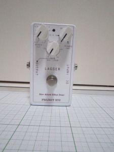
As a quick summary, Project Ryu Lagger is  a guitar effect pedal that slows down the attack of the guitar (or any instrument for that matter) just like an automated volume pedal.

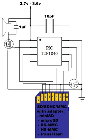
It does this with a VCA (Voltage Controlled Amplifier), based on the LM13600/LM13700. The fade in envelope is created with a ramp voltage generator that controls the VCA and this generator is triggered by a digital circuit created with a Microchip PI18F1320 MCU.

The digital signal conversion and rectification is explained in a previous article, please read it at the link below:

Project Ryu Lagger Guitar Pedal Take 3

Analog to Digital Signal Rectification

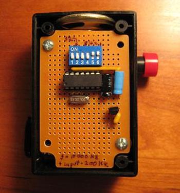
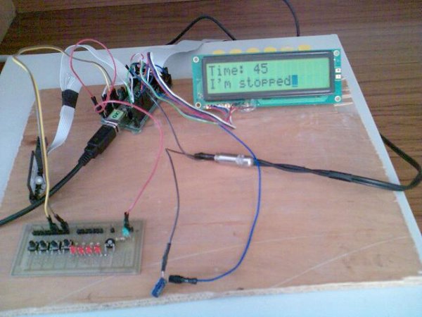
The new version i will present today was adapted as a real pedal with a 3 pole footswitch.

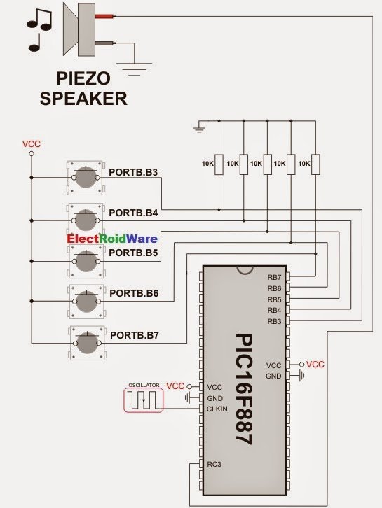
Another change was in the ramp generator replacing the 100k potentiometer with a 10k one since the other two pots in the circuit are 10k. This last change also implies changing some capacitor values. Please refer to the new schematics below:

Project Ryu Lagger Schematics

I am pretty satisfied with this pedal so i have created the PCB for this circuit. The PCB gerber files and the MCU firmware is available for free as usual to subscribers in the next newsletters. If you are not a subscriber yet please register in the form to the right.

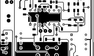
Some things to consider if you plan to design your own PCB is good shield of the LM13600/13700 input pins. It is good to surround it with ground plane like below:

You can find the PCB artwork below:

Project Ryu Lagger PCB Art

With the new modifications on the ramp generator circuit the min – max values for attack control is 0.1s and about 1.4s. Below is the ramp waveform measured, this is actually the control voltage of the VCA:

1. full counter clockwise attack pot setting:

Horizontal resolution: 50ms/div

2. full clockwise attack pot setting:

Horizontal resolution: 200ms/div

Below is a screenshot that shows the triggering of the ramp generator, the red trace is the input signal:

As you can see modifying the attack control will adjust the length of the fade in effect. The trigger control adjust the input level above which the ramp generator is triggered. This is to prevent noisy pickups or other pedals used in front of the Lagger to trigger the effect.

The level control adjusts output gain from between +6dB to a max of +24dB so it is capable of a high amount of gain. In the measurement below voltage gain is 14 with an output voltage of 3.6V peak to peak (yellow trace). As you can see there is a bit of saturation happening.

Bellow are two videos showing signal traces using sine waves at 1kHz, one video triggering the effect manually and the other with the effect triggered by the input signal.

Project Ryu Lagger is one of my favorite pedals, i really like this effect and the latest version allows for a great deal of control for the guitarist in sustaining the effect or muting by simply applying muting effects with the palm for example.


For DIY-ers this project is of moderate complexity but you can subscribe or comment here and i will try to offer any assistance i can. Remember to read the Disclaimer though.

Here is the parts list for this project:

Quantity: References Value
3 C1, C8, C15 4.7u
2 C2, C3 22p
1 C4 10u
1 C5 100u
2 C6, C7 33u
1 C9 4700u
1 C10 10u
2 C11, C12 1000u
5 C13, C14, C16-C18 100n
2 R1, R21 2k
13 R2, R6-R12, R15, R22, R23, R26, R28 10k
1 R3 22k
1 R4 3.3k
4 R5, R29, R31, R32 2.2k
3 R13, R14, R24 100k
1 R18 1k
1 R19 470
2 R20, R25 200
1 R27 5.6k
1 R33 1M
1 U1 LM13700
1 U2 PIC18F1320
1 U3 78L05
1 U4 79L05
2 U5, U6 TL071
2 Q1, Q2 BC549
1 Q3 BC559
2 D1, D2 1N4001
1 D5 LED
1 J3 3 pole foot switch
3 POT1-POT3 10k
1 RV1 1k
1 X1 20Mhz Crystal

I hope you enjoyed reading this article as much as i enjoyed building this pedal and hope to hear from you. To the subscribers, the newsletter will be sent in a few days with Gerber files for PCB and MCU firmware and a couple more details about this construction.

CEATEC 2014 Audio Report, TAD, Pioneer and Technics

This sure was a pretty full period audio-wise. Lots of events all over the world and im glad to say i pushed forward new developments with Project Ryu.

CEATEC Exhibition as expected was held this month and i was looking forward to some new audio products. Looking around i found Tamura Booth showing off their transformers.  In a glass box they also had one of their vintage jewels. Take a look:

Next interesting booth was Pioneer’s. A lot of demo DJ setups and noise but in a corner i found TAD. Nothing new here but i could snap a couple of driver close-ups of the Reference One Speaker System. Also they displayed the Compact Reference CR1MK2 but i got to say i was more attracted by a TL-1601a they had in between.

Next to TAD, Pioneer Professional (… i know)  showed their PA speakers. GS-WAVE Series sure look promising and it is a pretty interesting move for Pioneer to go back to the old days of PA with the concept for this series. Pictured below is the WAV-LENS, mid-high speaker featuring acoustic lens and can do a whooping 145dB peak. Coaxial 2″ drivers, 250W MF and 160W HF and dispersion measures 110 deg H and 50 deg V.

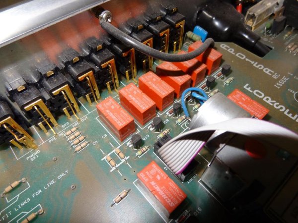
Technics had a very nice room, showing a bit of their history, had 2 listening rooms and they presented their Reference System R1 Series. Products were displayed with inside view as well.

The R1 Series has 3 components, SU-R1 Network Audio Control Player (aka Preamplifier), SE-R1 Stereo Power Amplifier and SB-R1 Speaker System.

Technics SU-R1 Control Amplifier is a 17kg preamp featuring Technics Digital Link (a digital connection between Technics Components) and it is powered by two R core power transformers.

Project Ryu Lagger Guitar Pedal Take 3SE-R1 Stereo Power Amplifier sure looks like it can handle the work load. Normally Technics tried to come up with something different and even if IMHO they really lack imagination naming these technologies, i really appreciate their effort. So SE-R1 features JENO Engine (Jitter Elimination and Noise-shaping Optimization) … [great name guys!], GaN-Fet Driver, (now this is something worth looking into) and LAPC (Load Adaptive Phase Calibration).

The third component of the R1 Series is the SB-R1 speaker system. Now in the past Technics has proven its speaker design ability with some really amazing products. Now on this blog i don’t really want to write subjective impressions on sound so if you are curious about this system go ahead and find a place where you can listen to them. And this goes for any system from any brand, its your money, if your willing to spend it go and decide for yourself.

What i can do is give you some pictures and info on how these systems are built. So back to Technics SB-R1, these speakers claim 100kHz , and they reach that but at -16dB! Oh well… so lets just throw away the specs and look at what we have here.

We have 4 x 16cm drivers in 2 separated bass reflex enclosures (2 per enclosures), we have 1 coaxial MF/HF unit which looks pretty interesting in its own isolated closed enclosure.

Below you can see a cutout through the speaker and some details like crossover board. As you can see there are no exotic components in the crossover.


For more detail: Project Ryu Lagger Guitar Pedal Take 3

The post Project Ryu Lagger Guitar Pedal Take 3 using pic microcontoller appeared first on PIC Microcontroller.


Create Musical Tone using PIC Code

$
0
0
The mikroC PRO for PIC provides a Sound Library to supply users with routines necessary for sound signalization in their applications. Sound generation needs additional hardware, such as piezo-speaker (example of piezo-speaker interface is given on the schematic at the bottom of this page).

Library Routines

  • Sound_Init
  • Sound_PlayCreate Musical Tone using PIC Code

Sound_Init

Prototype void Sound_Init(char *snd_port, char snd_pin);
Returns Nothing.
Description Configures the appropriate MCU pin for sound generation.
Parameters :
  • snd_port: sound output port address
  • snd_pin: sound output pin
Requires Nothing.
Example
// Initialize the pin RC3 for playing sound
Sound_Init(&PORTC, 3);

Sound_Play

Prototype void Sound_Play(unsigned freq_in_hz, unsigned duration_ms);
Returns Nothing.
Description Generates the square wave signal on the appropriate pin.
Parameters :
  • freq_in_hz: signal frequency in Hertz (Hz)
  • duration_ms: signal duration in miliseconds (ms)
  Note : Frequency range is limited by Delay_Cyc parameter. Maximum frequency that can be produced by this function is Freq_max = Fosc/(80*3). Minimum frequency is Freq_min = Fosc/(80*255). Generated frequency may differ from the freq_in_hz parameter due to integer arithmetics.
Requires In order to hear the sound, you need a piezo speaker (or other hardware) on designated port. Also, you must call Sound_Init to prepare hardware for output before using this function.
Example
// Play sound of 1KHz in duration of 100ms
Sound_Play(1000, 100);

Code Example

The example is a simple demonstration of how to use the Sound Library for playing tones on a piezo speaker.
 Create Musical Tone using PIC Code schematich
void Tone1() {
  Sound_Play(659, 250);   // Frequency = 659Hz, duration = 250ms
}

void Tone2() {
  Sound_Play(698, 250);   // Frequency = 698Hz, duration = 250ms
}

void Tone3() {
  Sound_Play(784, 250);   // Frequency = 784Hz, duration = 250ms
}

void Melody() {           // Plays the melody "Yellow house"
  Tone1(); Tone2(); Tone3(); Tone3();
  Tone1(); Tone2(); Tone3(); Tone3();
  Tone1(); Tone2(); Tone3();
  Tone1(); Tone2(); Tone3(); Tone3();
  Tone1(); Tone2(); Tone3();
  Tone3(); Tone3(); Tone2(); Tone2(); Tone1();
}

void ToneA() {
  Sound_Play( 880, 50);
}
void ToneC() {
  Sound_Play(1046, 50);
}
void ToneE() {
  Sound_Play(1318, 50);
}

void Melody2() {
  unsigned short i;
  for (i = 9; i > 0; i--) {
    ToneA(); ToneC(); ToneE();
}


For more detail: Create Musical Tone using PIC Code

The post Create Musical Tone using PIC Code appeared first on PIC Microcontroller.

Music player built on microcontroller AT91SAM7S256 with ARM core

$
0
0

1. The player allows:

  • playback wav files in stereo format, 22,500Hz freqfency, and 8 bits of resolution,
  • display the song titles,
  • display time of songs,
  • the possibility of stopping (pause) and switch songs,
  • the possibility of change volume (+, -),
  • read data from the MMC memory card inserted in the slot,
  • display current state on the alphanumeric LCD display,
  • the possibility set random order of songs

Music player built on microcontroller AT91SAM7S256 with ARM core

2. For the construction this system could be executed the following elements:

  • microcontroller AT91SAM7S256 from Atmel,
  • alphanumeric LCD display with HD44780 driver ,
  • keyboard with 4 buttons ,
  • memory-card slot,
  • memory card MultimediaMemory Stick (MMC) or optional SD card

Schematic Diagram

3. The principle of operation is quite simple.

a) data from the memory card
| SPI
b) uC SAM7S
| PWM
c) AUX

Ad. a) data from the memory card are reading by the module FatFS. It is necessery bacause on card is used FAT16, FAT32 format. We can playback a wav files, witch are stored on memory card. To store it you can use your PC. Read data are stored up to 2 buffers – it is required because the data may not interfere with the currently playing music.

FatFs module has been written in ANSI C, so it’s independent from the hardware layer and can be easily transferred to different types of microprocessors. Support for the card via the SPI is held by only 3 pins of the microprocessor – lines of data MISO, MOSI, and the clock CLK line. The card requires a power supply voltage of 3.3V, which is equal to the voltage of power processor SAM7S.

Ad. b) In microcontroller timer PIT is set to submit periodic interrupt reqest 22.5 kHz frequency – the frequency of sampling music files. The interrupt checking which data buffer is currently being used and the appropriate values of indexes are transmitted to the buffer registers PWM generator. These values representing 2 channels of sound (left and right). When the index of buffer reach the maximum length of the array the current buffer change, and the flag is set – to allow to write of the next portion data to another buffer.

Ad. c) The player uses 2 independent PWM channels, which are configured to work with a resolution of 8 bits, and the frequency of MCK / 8. The filling PWM generator is dependent on the data collected from the buffer, and is proportional to the voltage output corresponding to the I/O pin of the microcontroller.

The data are processing by uC AT91SAM7S256. It is a 32-bit architecture RISC processor type. SAM7S with ARM ARM7TDMI is one of most successful model.

Music player built on microcontroller AT91SAM7S256 with ARM core Schemetic

Some features of SAM7S256:

  • Internal High-speed Flash – 256 Kbytes Organized in 1024 Pages of 256 Bytes
  • Internal High-speed SRAM – 64 Kbytes
  • Reset Controller
  • AIC- Advanced Interrupt Controller
  • DBGU, 2-wire UART, 2 USART
  • PIT – 20-bit Programmable Counter plus 12-bit Interval Counter
  • RTT – 32-bit Free-running Counter
  • PIO – 32 Programmable I/O Lines
  • SPI – to 16-bit Programmable Data Length
  • One Three-channel 16-bit Counter
  • 1 Four-channel 16-bit PWM Controller
  • 1 8-channel 10-bit Analog-to-Digital Converter
  • Power Supplies – 3.3V

Downloads

Source code

pro-qwerty.com


For more detail: Music player built on microcontroller AT91SAM7S256 with ARM core

The post Music player built on microcontroller AT91SAM7S256 with ARM core appeared first on PIC Microcontroller.

NJM2035 – HI-FI Stereo Encoder / Multiplexer using pic microcontoller

$
0
0
Part’s List:
2x 47K
1x 10K
1x 82K
1x 50K POT
1x 33uF
1x 10uF
3x
100nF (104)
1x 100pF (101)
1x 10pF (10)
1x NJM2035 IC
1x 38 KHz Crystal
  Technical Specifications:
Voltage Supply: 1.2V – 3.6V MAX
Current Draw: >3mA
Channel Separation: < 25dB
Signal to Noise Ratio: 67 dB
Operation Temperature: -20 – 75°C
Frequency Range: 20Hz – 15KHz
NJM2035 - HI-FI Stereo Encoder MultiplexerHI-FI Stereo Encoder / Multiplexer
This stereo encoder is the perfect solution for those looking for a high quality stereo sound transmission at a low cost. This stereo encoder produces an excellent crystal clear stereo sound and very good channel separation that can match with many more expensive stereo encoders that are available on the market. It is all possible thanks to a 38KHz quartz crystal that controls the 19kHz pilot tone, so you will never have to calibrate or re-adjust the circuit.
NJM2035 offers superb quality and is manufactured by NJR CORPORATION (JRC), a subsidiary of New Japan Radio, a company that is known as the world’s best manufacturer of high end professional audio semiconductors. This transmitter will work with any mono FM transmitter including TX300 and TX500 which are available on our website. The whole circuit may easily fit on a small 1” x 1.5” printed circuit board allowing to fit in places where space is limited. While building your stereo encoder please take your time and always double check with the schematic to make sure that all the connections are done correctly. If you have any questions, comments or suggestion we will be glad to further assist you.

How Does Stereo Encoder Work?

The stereo encoder consists of three main stages; pre-emphasis, digital encoder and mixer stages.

Pre-emphasis stage is achieved by using two 47K resistors and two 1nF capacitors. This helps to eliminate the noise that is produced during the FM transmission of your audio signal.

Second stage that is built around NJM2035 is a digital encoder. All of its internal blocks except for two audio amplifiers (pins 1 & 14) that act as separators are created using digital circuits. The first digital circuit is a 38KHz oscillator that is generated by using external 38KHz crystal (pin 7), 10pF capacitor (pin 6) and 100pF bypass capacitor (pin 5). Once 38KHz frequency is generated it is then buffered and divided into two 19KHz signals with a phase difference of 180 degrees. Once that is done these two frequencies are connected with two time division MPX digital alternating switchers ,one for each audio channel. Here audio channels are switched between each other with a total frequency of 38KHz. If you would be able to slow this frequency to 1Hz per second you would be able to hear that this all but a trick. During the first half of the second you would hear the left audio channel and during the second half of the second you would hear the right audio channel. Due to the fact that the channels are switched with a fast frequency of 38KHz per second our brain is unable to recognize that these channels are really switched and receives this as a continuous audio signal. At the same time another signal from the 38KHz oscillator is divided by half into 19KHz. This signal is called a PILOT tone because it will help a stereo decoder on the receiver’s part to slice the MULTIPLEX signal (mixed L and R audio channels) and separate them back into left and right audio channels.

The third stage is a mixer that consists of 33uF and 100nF capacitors and 82K and 10K resistors. The role of this circuit is to mix the multiplex subcarrier and pilot signals together. The multiplex subcarrier signal that is coming out from the pin 9 of the NJM2035 IC is the sum and difference of both left and right audio channels that are switched at 38Khz rate. The PILOT signal that is coming out of pin 8 is a 19KHz frequency that is used to distinguish what channel is currently being switched and without which stereo decoding would not be possible.

NJM2035 - HI-FI Stereo Encoder MultiplexerHow to Connect a Stereo Encoder to your FM Transmitter

1) First test your FM Transmitter and make sure that an audio signal is properly transmitted on your desired frequency. Once that is done turn off your transmitter and disconnect its audio inputs.

2) Connect left and right audio outputs from your audio source to the inputs of your stereo encoder.

3) Connect stereo encoder’s MPX output to your transmitter’s input (audio coax cable highly recommended).

4) Turn on your transmitter, FM receiver and audio source (making sure its audio volume is not too loud), and apply voltage supply from a single 1.5 battery cell to a stereo encoder.

5) By now you should hear a stereo sound. Adjust 50K potentiometer making sure your L-R balance is set to the middle and adjust the volume of your audio source making sure an audio signal is as clear as possible.

For more detail: NJM2035 – HI-FI Stereo Encoder / Multiplexer

Current Project / Post can also be found using:

  • loading an audio into pic microcontroller
  • micro controller audio player

The post NJM2035 – HI-FI Stereo Encoder / Multiplexer using pic microcontoller appeared first on PIC Microcontroller.

ISD2560 Voice Recording Playback Project PIC16F84 Controlled

$
0
0

ISD2560 to directly control the PIC16F84A, audio recordings and multiple block will be able to play. LSI can be driven directly speakers also, in view of the lack of volume, only added to the amplifier IC. This volume 10 minutes to drive the speakers. One LSI chip for voice recording playback “ISD2560″ using a simple audio recording and playback unit prototype itISD2560 Voice Recording Playback Project PIC16F84 Controlled

ISD2560 is playing this voice recording, in the same basic configuration, the sampling frequency, Divided into the following series. The use of the series in the most wide-frequency band; Instead of recording time limited to 60 seconds.

PIC16F84 ISD2560 Voice Recording Project Schematic

The above configuration, PIC16F84 controlled CCS C program written in C language ISD2560 directly as a result. LSI around as a standard configuration, so as MDS. Address the problem of how to control, but trying to control all the bits and 10 bits will be necessary in the event. Therefore, a control unit 64 and the lower six bits is 0 and leave it. This control is not only necessary to address the 4-bit, and easy configuration.ISD2560 Voice Recording Playback Project PIC16F84 Controlled schematic Eventually 6.4 × 19 seconds blocks can be controlled. From the PIC, as well as switch addresses can be specified in order to make it possible to switch. The switch is using 4-bit DIP switch.

ISD2560 Voice Recording Playback schematic pcb PIC16F84 code files download: isd2560-voice-recording-playback-project-pic16f84-controlled.rar alternative link2


For more detail: ISD2560 Voice Recording Playback Project PIC16F84 Controlled

Current Project / Post can also be found using:

  • pic18f4520 speaker code
  • how to analyze audio signal using pic microcontroller
  • pic of sounf

The post ISD2560 Voice Recording Playback Project PIC16F84 Controlled appeared first on PIC Microcontroller.

PIC16C63 Midi controlled Light dimmer

$
0
0

This is Ver2.0 of a finished project.

I usually do projects about the same way every time. Product definition (10 min), Code outline (10 min), Schematic generation, Build prototype, Write code all at one sitting (This one took about 6 hours), Take a copy of the above file, and delete all but a small section. Debug the section, and put it back into the original file. Repeat with other chunks of code until done. Test the program as a whole, Mass produce and be famous (never got to this last step yet).

pic16c63-midi-controlled-light-dimmer

Files in MIDI.ZIP

MIDI20.C Source code for Midi Light dimmer

MIDI.SCH Schematic in OrCad Version IV (Dos version)

MIDI.LIB Library file for OrCad Schematic

MIDI.DXF Schematic in DXF Format

MIDI_SCH.PDF Schematic in Postscript format…. Copy to postscript printer

Download “MIDI.ZIP” PIC16C63 C source code and schematics.

View Schematic for the MIDI light dimmer (PDF File).

View Photo of finished product.

MIDI Nomenclature is as difficult to describe as it is to spell.

Use the terms Port, Channel, Device, and Box like this. You can have lots of MIDI ports (Connectors) on a machine. Each MIDI PORT can have 16 CHANNELS of 127 DEVICES (notes) each. Each light dimmer box consumes 5 DEVICEs: 4 lights and one relay.

As it is, the box has a MIDI interface. There’s an input connector and an output connector. The boxes’ output connector goes downstream to the next boxes’ input connector. There’s a DIP switch in each box to select which of the 16 channels the box will respond to, and what device the first light will respond to. The four lights and the relay will respond to four consecutive device addresses. So… With the dipswitch, you can set a box to be on channel 5, and use devices 32 thru 36. The first light will respond to device 32, the next light device 33, the next 34, and the last 35. The relay will then use device 36. You can connect another box to the first box’s output connector, and set it to respond to channel 5 devices 37-41, (or any channel, any device).

Cakewalk is a MIDI sequencer / editor and it is good. You can just draw the desired intensity of a particular light by drawing a volume envelope of a single note. If you’re in a stage act, and already have Cakewalk doing the sound, that’s the way to go. The existing design can be modified to use standard baud rates, and the RS-232 Electrical interface. Then you can just fire off commands via RS-232. Cakewalk would be a little difficult to interface to if you just wanted to make a home lighting system that responds to opening doors and time of day. For that you just wip something up in Visual basic using standard com port commands.

PIC “Pinewood Derby” style race timer.

PIC based “Pinewood derby style” race track timer. One switch closure starts the race and initiates end of race process. That switch is mounted to the starting gate. When the gate snaps open, the cars start rolling. The gate stays open until the race is over. The act of closing the gate, clears the timers, sets the state machine, and process flags to be ready for the next race. Digital inputs to indicate finish line crossings, one for each of four lanes. A digital high is output by the track when a car shadows the light detector at the finish line. This timer detects the rising edge of this signal. 11 bits of output are consumed by the 8 bit interface to a 2 line, 40 char LCD. There’s plans for a RS232 output to squirt the race times out a serial port. The timer is a great use during car tune-up. It doesn’t seem to add much to a race.


For more detail: PIC16C63 Midi controlled Light dimmer

Current Project / Post can also be found using:

  • Home automation using PIC 16F877A microcontroller
  • automatic door opening system using pic microcontroller
  • home automation with microcontroller

The post PIC16C63 Midi controlled Light dimmer appeared first on PIC Microcontroller.

Viewing all 110 articles
Browse latest View live