Quantcast
Channel: Sound - Audio Projects - PIC Microcontroller
Viewing all 110 articles
Browse latest View live

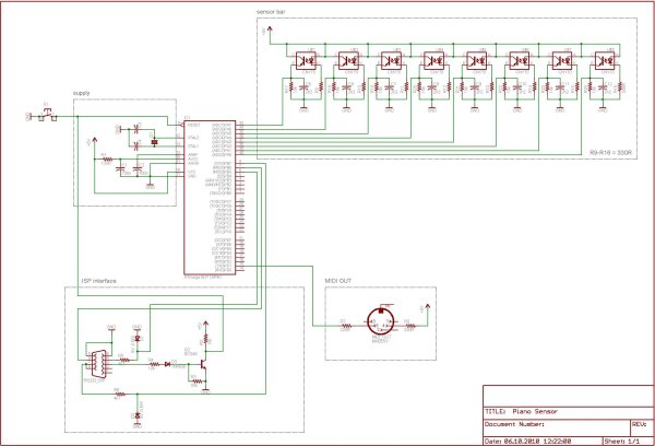
LED-Guided Piano Instruction using pic microcontoller

$
0
0

[Kay Choe] can’t play the piano. Rather, he couldn’t, until he converted his keyboard to include LED-guided instruction. [Kay] is a microbial engineering graduate student, and the last thing a grad student can afford is private music lessons. With $70 in components and a cell phone, however, he may have found a temporary alternative.

The build works like a slimmed-down, real-world Guitar Hero, lighting up each note in turn. We’ve seen a project like this before, with the LEDs mounted above the keys. [Kay]‘s design, however, is much easier to interpret. He embedded the LEDs directly into the keys, including ones above each black key to indicate the sharps/flats. An Android app takes a MIDI file of your choice and parses the data, sending the resulting bits into an IOIO board via USB OTG. A collection of shift registers then drives the LEDs.
LED-Guided Piano InstructionFor a complete novice, [Kay] seems to benefit from these lights. We are unsure whether the LEDs give any indication of which note to anticipate, however, as it seems he is pressing the keys after each one lights up. Take a look at his video demonstration below and help us speculate as to what the red lights signify. If you’re an electronics savant who wants to make music without practicing a day in your life, we recommend that you check out [Vladimir’s] Robot Guitar.
Filed under: Android Hacks, led hacks, musical hacks

Reposted by RK

September 22 2013

The post LED-Guided Piano Instruction using pic microcontoller appeared first on PIC Microcontroller.
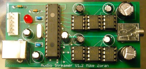

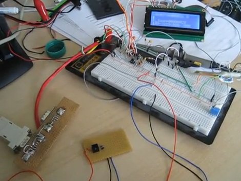
USB Audio Streamer A Microchip PIC based USB sound card

$
0
0

INTRODUCTION

The idea for creating a USB sound card based on a PIC came from discussions of other people creating one on the Microchip USB forum. The hardware of the card is based on all Microchip products. The software uses a modified version of the Microchip USB framework which is interrupt driven instead of the traditional polling. The device is a USB composite device. The first device is an implementation of the USB Audio 1.0 interface and the other device is a custom interface based on a HID interface. The purpose of the custom interface is for programming the device serial number, upgrading the firmware, and in the future any other configuration that isn’t supported directly by USB Audio 1.0. In a previous version, WinHTTP was oringally used. After testing the card for awhile, I decided it’s better to not require drivers for the card especially since the HID/WinUSB interface is rarely used.

The sound card runs at a sample rate of 48KHz, 32KHz or 24KHz selectable by the OS with 12 bits per sample. The quality approaches commercial grade as the sample rate is higher then CDs. 44.1KHz was not implemented due to the difficultly and additional processing overhead. The sample rates that were implemented are all a multiple of the 1ms USB frame meaning each frame sends the same amount of data. 44.1KHz requires the card to handle different amounts of data each frame requiring more advanced buffering and synchronization techniques and more processing power. Microsoft Windows automatically resamples the 44.1KHz audio found on CDs to 48KHz.USB Audio Streamer A Microchip PIC based USB sound card

HARDWARE

The hardware for the sound card is based on the Microchip PIC18F2550 USB processor. The processor is clocked at 48MHz which is the maximum rate for this processor and is also a multiple of the audio sample rate. The microcontroller is connected via the SPI port to duel Microchip MCP4822 12bit D/A converters. Volume control is implemented by the Microchip MCP41010 variable res– ders are controlled via SPI by the microcontroller via a dedicated bit-banged SPI port. The purpose of using a separate port is so that volume control can run inside the processor at a different priority level then sample output. The Microchip MCP6022 op-amp is used as an output driver.

The MCP6022 op-amp has an output drive capacity large enough to power a pair of cheap headphones without much distortion. The resistance of my headphones is approximately 25ohms. The op-amps are not powerful enough to drive speakers which are usually 8 or 4 ohms. The MCP41010 and MCP6022 can output near rail to rail voltage although some nonlinear effects can be heard if the volume is too loud or the signal is near the minimum or maximum. Since USB has a single rail 5V power supply, the sound card only uses a positive rail instead of a traditional duel rail system which is how standard 16bit PCM is encoded. As a result, the signal needs to be biased in software to 2.5V.

One terminal of the MCP41010 is connected to the signal for that channel and the other terminal is connected to the midpoint or bias voltage. Previous versions of this sound card connected the second terminal to GND. The advantage of connecting the terminal to the bias is that as the volume is changed, the signal grows or shrinks around the midpoint rather then shifting toward GND. The signal is kept as far away from the rails as possible.

SOFTWARE

The software for USB Audio Streamer is composed of several components. These are the audio card firmware, a C++ library that wraps HID and WinUSB, and a command line utility for flashing. I am giving out the source code as a learning tool for other people. I don’t care what you do with it but I am not responsible for any damage that might happen from using it. NOTE: Improper use of hardware or software may cause serious injury or death.:)

I use Visual Studio 2005 Professional but I have heard that the project will build with Visual Studio Express. To build the project it is necessary to download the latest version of the WDK to get the headers and library files for HID and WinUSB. The default directories in Visual studio need to be modified to point to the directories of these resources in the WDK. If you use Visual Studio Express it’s necessary to recreate all the project files and change the default calling convention to _stdcall.

Directory     Function
inc     General Include Directory
boot     Boot Loader(Build first)
audiostream     Sound card firmware
usbdevprogramer     Programmer command line utility(Build last)

A trick is used when building the sound card firmware since it is two separate projects that need to be merged together. Build the boot directory first, which is the code responsible for upgrading the firmware. Then build the sound card firmware itself. Before flashing, goto Configure/Settings/Program Loading and clear the option to clear program memory upon loading a new program. After the sound card firmware is build, goto file/import and import the hex file for the boot loader. The two projects will be merged together without any cutting and pasting. At this point, it is OK to flash the PIC. Note the bootloader is only necessary for flashing firmwares without a ICD/Pickit. When debugging actual card functionality, it’s ok to leave out the bootloader. This Requires no modifications to the sounce or linker scripts. Simply don’t merge the boot loader into the imageUSB Audio Streamer A Microchip PIC based USB sound card schematic

SOUND CARD FIRMWARE

The sound card firmware is based on a modified version of the Microchip USB framework. The framework has been collapsed into a single source file with callbacks between the framework and the main code. The framework( in my case it’s more of a library ) has been modified to use interrupts instead of the traditional polling method. Instead of calling USBDriverService in a loop, this function is called whenever the USB interrupt fires. The library is response for handling control requests on endpoint 0. The framework handles standard USB requests and the body code is responsible for handling class specific USB requests nonstandard requests. The body code is responsible for handling I/O on all other endpoints.

USB Audio Streamer is a composite device of a USB Audio 1.0 device and a custom HID interface. With USB Audio 1.0 all of the sample data is transferred through a separate endpoint then control requests. Control requests such as controlling volume is through endpoint 0(the control endpoint.) HID uses it’s own endpoint. Since each function of the card has a separate endpoint, each of the functions can be implemented at a different priority level without preemption problems. The PIC18F2550 has two interrupt priorities plus the main handler. This gives a total of three priorities. Since playing sound data is the most critical function it was given the highest priority. Next comes control endpoint requests which include the standard requests plus Audio 1.0 requests. Since these functions have relatively low timeouts, these were assigned low priority. HID functions are in the main body code because actions such as querying the firmware version, settings the serial number, or flashing the firmware are not time critical at all.


For more detail: USB Audio Streamer A Microchip PIC based USB sound card

Current Project / Post can also be found using:

  • how to include sound in microcontrollers
  • microchip mp3 player
  • microcontroller for audio projects
  • voice using pic 16f877a

The post USB Audio Streamer A Microchip PIC based USB sound card appeared first on PIC Microcontroller.

Project Ryu Lagger – Guitar Effect

$
0
0

Do you remember BOSS Slow Gear pedal? If your a guitarist you most likely do or at least you’ve heard of it. It was a great pedal sold from 1979 to 1982 and it was made in Japan. The pedal would cut the attack of your notes giving a swelling sound. It god famous for making the guitar sound kinda like a violin.

I always liked that effect and i even made a clone a few years back. It is based on a 2SK30 JFET and it was a pain getting these transistors. It was a lot of fun though and i though i should make a Project Ryu swell effect pedal and so LAGGER was born!

Project Ryu Lagger – Guitar EffectRecently i worked on a few projects with LM13600/LM13700, one of them is a nice noise gate / compressor unit which i will present at a later date, and i really like the VCAs that can be built with these chips.

To cut the attack of a note and then swell the volume basically we need a triggered fade in effect. This means that we need to control our VCA with a rising voltage using what i call a ramp generator.

In a previous article (Monitoring Amplifier モニターアンプ P3: Speaker Coupling Delay)   i described the circuit of such a ramp generator and it even has a command input. I will use this circuit with the LM13600 VCA all controlled digitally with a PIC18f1320.

The input is fed into an ADC channel to be rectified and averaged in order to detect when a note is played. Once it is detected, the ramp generator is triggered and provides the control voltage for the first VCA.

Project Ryu Lagger – Guitar Effect SchematicLM13600/LM13700 is a dual amplifier the second one is configured as a VCA with manually set control voltage. In the picture below you can see how the circuit works. The top signal is the input signal, the middle signal is the output of the ramp generator and the bottom signal is the trigger.

There is a problem with using the ramp generator circuit this way. The capacitor is discharged too quickly when the trigger is interrupted and this causes an audible thump noise when trigger goes off. Looking below at the schematic we can see the discharge current goes through CE junction of Q1.


For more detail: Project Ryu Lagger – Guitar Effect

Current Project / Post can also be found using:

  • audio record microcontroller
  • microcontroller engine sounds
  • microcontroller music
  • songs for microcontroller

The post Project Ryu Lagger – Guitar Effect appeared first on PIC Microcontroller.
SD/SDHC CARD SOUND RECORDER

$
0
0

Updated on 30.6.2015
The PIC16F876A’s ADC
digitizes the sound and store it in the SD or SDHC card. The firmware works for SD or SDHC cards only, for old SD (before 2009) use ver1 firmware. Do not use SDXC cards with this project because some of them work on 1.8V drive. The code detects whether the card is SD or SDHC and selects the proper addressing system for the card.
The PIC’s CCP is used as a DAC to convert the digital data back to audio. The sound is converted to 20KHz 8 bits mono in a format similar to .wav files. The quality of the audio is reasonable.
SD card interface the PIC in SPI mode. Reading and writing data is in multi-blocks. Memory is used at the rate of 20KB/s. The Error LED indicates error sent by the SD card. The software doesn’t use any file system, it just uses absolute memory addresses (raw). Since the programme is less than 680 bytes there is much resources left for adding features.SD SDHC CARD SOUND RECORDER
Audio input is 1Vp-p , you can use the mic circuit or other source. The CCP in PWM mode gives 20KHz wave with duty cycle modulated to the audio amplitude. A low pass filter removes the 20KHz component. I added a simple 2 transistors amplifier to boost the power to drive 32 Ohm speaker or headphones

  • SD/SDHC CARD FAT32 WAV PLAYER

This project is for .wav file type player (no recording). The software has the functions needed to read SD/SDHC card formatted in FAT32. The software can play only PCM 22.050KHz, 8 bits, mono. The bytes from the file are streamed to CCP1 (PWM mode) and with an external low pass filter you get the audio. The sound quality is OK for speech or medium quality music.
The software searches for files entries in the root directory only, it streams any file type without reading its name or type.
The circuit diagram is the same as the SD Sound Recorder minus the components for recording. Drawing is included with the software zip.
TO SET UP THE CARD:
Format the card with FAT32.
Create sound files type .wav
Name the files with short names, 8 low case characters max.
Save the files as 22.050KHz, 8 bits, mono.
Add the files to the root directory of the card (don’t use a subdirectory)

  • SD/SDHC CARD SOUND RECORDER 3.3V PIC16F690

This sound recorder has the same characteristics as the sound recorder with PIC16F876A. The difference is the supply voltage is 3.3V. This makes the direct drive of the SD card simpler. It also makes it easier to power it from a battery.
8MHz internal oscillator is used, if the frequency drifts it causes the playback to change speed. I left pins 2 and 3 free in case I have to use crystal oscillator.
The programming of the pic can be with 3.3V, if you have a pic programmer for 5V only remove the SD card while 5V is connected to the circuit, 5V will damage the SD card.

  • SD/SDHC CARD FAT32 WAVE PLAYER 3.3V PIC16F690

This wave player has the same characteristics as the wave player with PIC16F876A. The difference is the supply voltage is 3.3V. This makes the direct drive of the SD card simpler. It also makes it easier to power it from a battery.SD SDHC CARD SOUND RECORDER schematic
The playback speed can be changed by changing the time of TMR0 in the code.
The programming of the pic can be with 3.3V, if you have a pic programmer for 5V only remove the SD card while 5V is connected to the circuit, 5V will damage the SD card.

Troubleshooting: If the Error LED is on immediately on power up it means that the card failed to initialize. This code works for SD card rev 2 or SDHC card, it doesn’t work for SDXC (1.8V) or MMC or SD rev 1 cards. If your card is SD rev 1 you can use my firmware ver 1.
I’ve tested my code on 3 cards only and it may not work for all the cards, try using another make of card.

For more detail: SD/SDHC CARD SOUND RECORDER

Current Project / Post can also be found using:

  • audio input selector using pic ic
  • pic based piano

The post SD/SDHC CARD SOUND RECORDER appeared first on PIC Microcontroller.

MIDI Chord Button Keyboard Using PIC18f4620 part 1

$
0
0

Every time I sit down to document one of my projects, I try to remember the occasions in the past when looking at the finished web page, I might say ‘Well, I won’t do that again!’, because despite how many drafts I’ve gone through, there is always some aspect of the presentation that fails to measure up to my expectations. Then there’s the question of boredom. I don’t want all my project pages to look exactly alike, just reasonably easy to look at and above all else accurate. Finally, there is the thorny issue of the media itself. Most will realise that these pages are formed using WordPress php code, with a few (very few!) additional pieces of my own php. Presentation using combinations of tables, pictures and lots of text hits size problems which I don’t understand, and moreover, I’m unwilling to spend hours, even days trying to fix, so that there is a finite limit to some post lengths. Rather than pushing the boundaries, and risk the non-presentation of a post, I intend keeping each article instalment reasonably small in future. This will also cut down the loading time from the http://joebrown.org.uk/wp root, which several users have noted has grown a little too long lately!

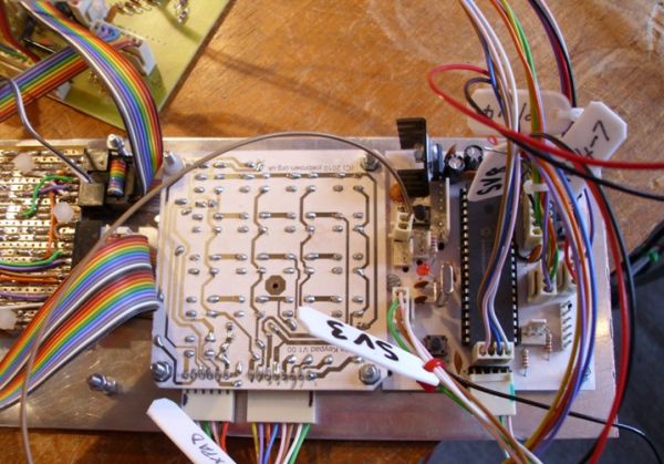
Hexpad and processor board

The article presented here documents an update of my MIDI Chord Button unit described originally on connectable.org.uk. That article used a 28 pin PIC and was written in PIC assembly language. The unit is still in use, and I decided to build a bigger, hopefully better unit, and write the code in ‘C’.

The unit supports a button matrix of (up to) 20 columns, by 8 rows. Each column is a particular musical key e.g. Ab, and each row a chord type, e.g. Maj7th. A momentary-action shift key provides for a further 8 chord types.

The basic mechanism for scanning the matrix is essentially the same as in the original article, and I don’t want to repeat work, simply for the sake of it. Those of you contemplating basing your own project on the following are urged to read the original article.

For the uninitiated, the 20 key columns are arranged in a virtual ‘circle of fifths’. Which means that if you learn a chord sequence, you can transpose up or down the keyboard and play the same sequence again in a different key. This is very similar to the stradella layout of some Italian chord button accordians, and makes a lot of sense, being relatively easy to play.

There is a table of the columns and keys in the original article, but I’ve provided a sample set of panels for the matrix, so make no excuses for showing the new layout here.

I’ve drawn the unshifted chords available on the LH side of the buttons and the shifted chords available on the RH side of the buttons, this has been repeated at each 4th multiple of the columns only, so as to reduce eye strain!

The small table below shows the layout in schematic form, with the base note value for each key/chord combination (given in hex). Note that the keys marked with the suffix ‘1′ represent an octave key – i.e. a musical key that is also further down the keyboard. Also note that I’ve followed the convention of the accordian and renamed the octave keys for Db as C#, Bb as A# etc. If you are confused, look at the base note values given, these will show the relationships.

Perhaps the best thing about a home-built instrument is that you can mash it up to do exactly what you want, and not what some manufacturer (or people like myself) think you want.


For more detail: MIDI Chord Button Keyboard Using PIC18f4620 part 1

The post MIDI Chord Button Keyboard Using PIC18f4620 part 1 appeared first on PIC Microcontroller.
MIDI Chord Button Keyboard Using PIC18F4620 part 2

$
0
0

How chords are formed
Before discussing the processor board and software, it is worth mentioning how the chords are composed. I have provided the table below which shows the installed chords together with the intervals/notes they are constructed from, and examples of each in the key of C major.
Since the source-code is provided, and heavily commented, you can experiment, both with the actual chords installed, their placement on the matrix, and whether they will belong to the default or shifted group.
It is also likely that you may want to ‘open’ out some of the Phat Chords. I have left these in their minimum span configuration.
Slash Chords are not catered for on this unit, but a separate pedal-board is being developed which could be used to provide this facility.

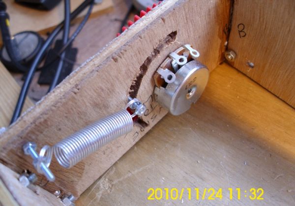
Pitch Wheel inside

Chord Controller Board

The chords are produced by scanning a matrix of switches to produce a unique value for each chord comprising the key value of the chord (eg. C#) and the chord value (e.g. min7). The switch matrix is scanned by the matrix decoder board, (see part 1: MIDI Chord Button Keyboard Using PIC Microcontroller) and when a switch close is detected, a TTL ‘low’ is placed on connector SV7 which is connected to RB1 of the PIC Microcontroller on the Controller board, the schematic of which is shown below.
Note that this controller is dual-purpose. For the chord-controller, IC2 – the CD4073 is not required, and it should not be installed.
On the right, SV1 and SV2 carry the address lines to the matrix decoder, Power is also supplied to the matrix encoder board via SV4. The MIDI OUT signals are provided on SV9, whilst the command hexpad, RESET, and LED connections are via X3,SV3, SV6 and SV8.
Both pitch wheel and velocity/volume control are provided for, and these interface to SV10 and SV11. A connector pin on SV8 allows for the connection of a chord-shift switch.
Note that the Analog channels AN0-AN5, and the digital pins associated with these are not used in the design, but code is installed to read each of the analog signals and may be used to provide extra controller interfaces if desired.

Mapping Commands
As an example of how I mapped my hexpad to control the unit (and the connected synth) I append a code-snippet here of the main interpreter.
First of all the hexpad keyvalue is translated from it’s raw scan value then processed. The digit keys 0-9 are passed on without further action except for designating the keytype as DECIMAL_VAL.
The left-hand-side and bottom-row peripheral keys (except for zero) are assigned specific functions/roles, and control passed to a relevant routine as required.
I will discuss various code routines later.


For more detail: MIDI Chord Button Keyboard Using PIC18F4620 part 2

The post MIDI Chord Button Keyboard Using PIC18F4620 part 2 appeared first on PIC Microcontroller.
Bluetooth-Controlled Guitar FX Amplifier

$
0
0

As part of our final project for ECE 4760: Digital Systems Design Using Microcontrollers, we built a guitar amplifier with remote distortion and digital effects capabilities controlled from a smartphone via bluetooth.

Musicians often need to modify the configuration of their amplifiers when performing in concerts. This job is generally delegated to “roadies” who walk on-stage between sets to make adjustments. By building on top of generic amplifier circuitry we’ve been able to increase the capabilities of the standard guitar amp to allow remote control over all aspects of the amplifier’s sound.

Bluetooth-Controlled Guitar FX Amplifier

High-Level Design

Things I Can Do
  • Interface via bluetooth with smartphone
  • Perform Digital Effects
  • Modify bass, treble, and mid with physical knobs
  • Modify bass, treble, and mid digitally


There are two methods of interfacing with the amplifier. The first resembles a classic guitar amplifier where the user controls the analog effects via knobs connected to analog potentiometers. As is standard, the input of the amplifier comes from a ¼” TS Male Auxiliary cord attached to an electric or acoustic guitar. We have a ¼” TS female to 3.5 mm TRS male adaptor. This in turn connects to a 3.5 mm adaptor which is wired directly into our circuit.
The second style of interfacing with the amplifier is via the PIC32 microcontroller which controls and applies digital effects. These sound effects are outputs of a Belton BTSE-16 chip, which, through onboard DSP, synthesize various effects. These effects include chorus, flanger, phaser, tremolo, delay, reverb, and various combinations thereof.

As part of our ‘stretch goal’, the primary standard to which we’ve conformed is determined by the Bluetooth Special Interest Group (SIG). The standard for Bluetooth that we will be following is set by IEEE 802.15.1. The standard essentially sets the MAC addresses available for our use as well as limits our applications to the 2.4-2.485 GHz ISM band.

Analog Circuitry

A large portion of the project was devoted to building and testing standard analog circuitry for generating our desired effects. The schematics for these are included below.

Distortion

Our input goes through a common emitter amplifier with the 10k and 100k resistors deciding the gain of the circuit. The 100 nF and 10 uF capacitors decide the frequency response of the circuit with a lower input capacitance creating a more treble-heavy sound and a higher input capacitance creating a more bass-heavy sound. The schottky diodes act as clipping diodes creating the distorted sound we hear at the output.

Tone Stack

Our input goes through a high pass filter into a unity gain op amp (pins 1,2, and 3). The treble potentiometer adjusts a high-pass filter that sets the cutoff frequency below which no frequencies can pass. The bass potentiometer adjusts a low-pass filter that sets the cutoff frequency above which no frequencies can pass. The mid potentiometer acts as a band-pass filter that amplifies the center frequency about which treble and bass act. The level potentiometer changes the magnitude of the output signal by altering the gain of the second op-amp (pins 5, 6, and 7). Pins 4 and 8 are the ground and Vdd (8.84 Volts) of the op-amp respectively.This schematic was found on Run Off Groove. We modified the circuit to use LF353 op amps, as they gave the desired performance and were readily available.

Class-D Amplifier

We used a TPA3122D2 15 Watt Class-D power amplifier in order to drive the signal to our speakers. The class-D amplifier uses pulse width modulation to take our analog input signal, convert it into pulses, and amplify the signal. In order to set the voltage high enough to drive the speaker, a capacitor is placed between the FET-driven output and the bootstrap pin. The amplified pulse train is converted back into an analog signal with the passive low-pass filter (capacitor and inductor) out of the ROUT pins of the chip (pins 12 and 13). This low-pass filter acts as an integrator to the PWM. Finally, we add DC offset to our signal with our 470 uF capacitor in order to output a audible signal to our speakers, without negative output.

Digital Circuitry and Microcontroller Integration

An even greater portion of the project was dedicated to digital design and microcontroller programming…

Digital Effects Chip

The BTSE-16FX effect board provides 16 different digital audio effects when integrated into the amp. On the highest level, the chip takes in an input signal (sound wave), a 4-bit binary select signal, and outputs an affected signal. The schematic shown to the left demonstrates one way to set up the chip which involves stepping down a voltage to power the chip, filtering an input signal, and filtering the output signal. We modified this schematic by replacing the input voltage circuit with a simple 5-volt power supply, replacing the input filtering with a simple high-pass filter, and removing the output circuit entirely by operating directly on the output of the chip.

The 4-bit binary select signal for choosing an effect was generated directly off the Pic32. A user would make a choice for effect via his or her smartphone, and the resulting bluetooth signal is read via uart and translated to a 4-bit logic output.

HC-05 Bluetooth Module

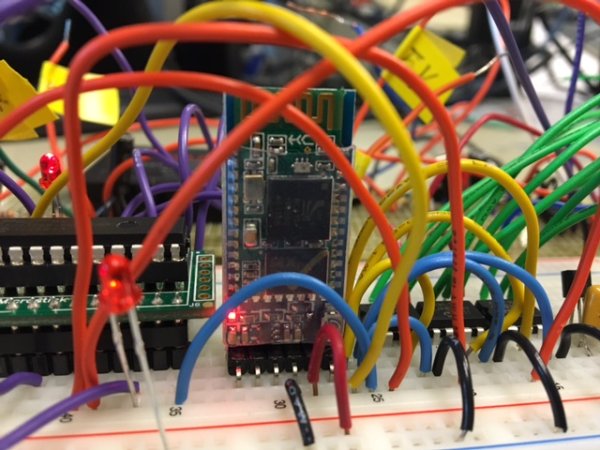
The HC-05 bluetooth module handles almost all responsibilities associated with establishing a bluetooth connection with any other bluetooth-enabled device. The HC-05 communicates over UART with the PIC which both transmits and received data. The chip works by publishing a bluetooth service and allowing another client – the smartphone – to pair with the module. Through the use of a bluetooth terminal on a smartphone (eg. blu-term) one can send data and test the uart connection with the PIC.

Read More:   Bluetooth-Controlled Guitar FX Amplifier

The post Bluetooth-Controlled Guitar FX Amplifier appeared first on PIC Microcontroller.
LM386 based stereo audio amplifier with digital volume control

$
0
0

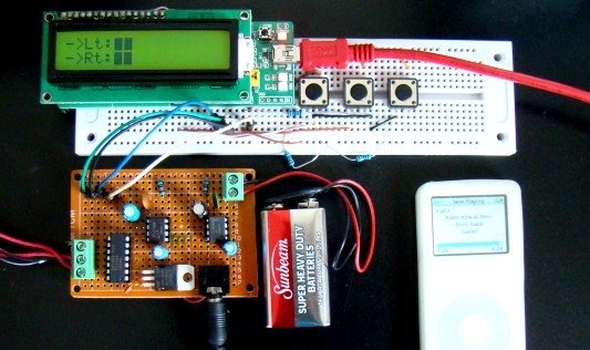
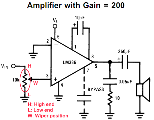
Due to its simplicity (requires minimum external components) and high availability, LM386 is very popular among hobbyists for use in low-voltage audio amplification applications. Most of the time a potentiometer is used at the input side of LM386 to provide a volume control in the output speaker. The potentiometer does not control the gain of the amplifier itself, but it creates a voltage divider network at the input, which in fact controls the fraction of the audio signal that is fed to the amplifier. This project is about a stereo audio amplifier using two LM386 ICs with digital volume control for both left and right speakers. So, how would you control the volume digitally? You are right, by replacing the traditional electro-mechanical form of potentiometers with digital potentiometer chips. This project uses MAXIM’s DS1868 dual digital potentiometer chip and a PIC microcontroller to control the volume of a stereo output from two LM386 ICs.

LM386 based stereo audio amplifier with digital volume control

Stereo audio amplifier with digital volume control

Theory

Tons of resources can be found on the internet about LM386 and so I am not going to describe it in detail here. The LM386 IC has got 8 pins which require very few external components to work as a mono amplifier. The circuit below is taken from the datasheet and shows the external components required for constructing a mono-channel audio amplifier with LM386. An external 10K potentiometer at the input is used to control the volume of the output speaker. For a stereo audio amplifier, we need two of this circuit.

Schematic LM386 based stereo audio amplifier with digital volume control

LM386 audio amplifier circuit

The supply voltage range for LM386 is wide (4-18 V). It can be powered with a +9V PP3 battery. For digital volume control feature, we will replace the external 10K potentiometer at the input stage with a digital potentiometer chip. MAXIM’s DS1868 is a dual digital potentiometer chip. Each wiper terminal has 256 positions between the high and low end of the potentiometer. The wiper position is set by an 8-bit control value that is stored into the I/O register of DS1868. The communication with the host microcontroller is done through a 3-wire serial interface. Please read my previous post, ‘How to interface MAXIM’s DS1868 digital potentiometer with a PIC microcontroller‘ for further detail on DS1868.

For more detail: LM386 based stereo audio amplifier with digital volume control

Current Project / Post can also be found using:

  • pic sound 16f877
  • audio ic microcontroller control
  • make sound with pic 16f877 and phone
  • sound meter using a pic

The post LM386 based stereo audio amplifier with digital volume control appeared first on PIC Microcontroller.

Record+play fast 1bit sound on a PIC!

$
0
0

BTc “Binary Time constant” algorithm.

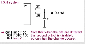
A system to record and/or play sound in a bitstream format using just one digital output pin.

This is a sound playback system for a PIC or any other
microcontroller. It uses a clever encoding system to
mathematically model the actual performance of the RC filter
when the signal is encoded. This allows playback of good
quality sound with the absolute minimum software and
hardware.
The RC filter modeling (encoding algorithm) has been
refined to be PIC friendly in binary math, giving the
ability to playback AND RECORD in real time even on
a PIC, even with high rates up to 150+ kbit/sec.

The playback hardware is:
1 PIC digital output pin
1 resistor
1 capacitor
This makes it suitable for adding to small and low-cost
products, providing speech or sound confirmation of
keypress, talking PICs, sound record/playback devices,
etc.

Record+play fast 1bit sound on a PIC!Playback theory:

With this system sound playback only requires an RC
filter, and speaker, earphone socket etc.

Sound playback is very simple and fast. Data is a
single stream of bits, at a constant rate. The PIC
only needs to output one bit, on one pin, at a regular
timed rate to make the sound or speech.
Sound can be added to an existing PIC project, if
one pin and a few instructions each interrupt are
available.

Of course a digital output driving a simple RC filter 
is a common system, used in a number of cheap
applications, but it has drawbacks due to the RC time
constant giving a non-linear waveform.

My BTc algorithm provides a simple fix, and is fast
enough that it can do real-time compensation during
encoding. The math modeling of my encoder maintains a
model of the RC filter with zero accumulated error. If
the bitrate is high enough this system will give
CD-quality audio, due to the PWM effect of the dithering
output, and the RC filter linearity problem is fully
pre-compensated by the math modeling in the encoder.
So the player doesn't need any math. :o)

Encoding theory:

Encoding the sound is the hard part. The stream
of bits must be chosen correctly so that the final
output waveform is as close as possible to the original
waveform.

But the actual output waveform depends on the electrical
characteristics of the RC filter, ohms, uF etc.
We can make the voltage on the RC filter rise by sending
a "1" bit, or fall by sending a "0" bit, but unfortunately
the voltage doesn't rise or fall by an equal amount for
each bit... A form of compensation is needed to make
the filter produce the correct waveform.
Encoding methods.
In order to make the final playback waveform the
closest reproduction of the original waveform I tried
some closed-loop encoding systems, starting with the
two most obvious types of encoding;

REACTIVE:
If sample is higher than math model make a 1 bit.
If sample is lower than math model make a 0 bit.

PREDICTIVE:
In math model, make both bits, "predicting" each
result. Then pick the bit that gives the output
closest to the desired sound sample.

Reactive is easier with only one model needing to 
be generated with each bit. Predictive works a lot
better with all the sound samples I tried. I only used
the predictive algorithm in my encoder program.
Actually, I did support the reactive algorithm too,
but deleted it later when it proved inferior.

The trick is getting a fast and accurate math model
generated, especially fast enough for high speed
bitstream recording/encoding on a PIC.

BTc Encoding Algorithm:

I haven't seen this BTc algorithm used or claimed by
anyone, it is basic encoding methodology, just done
in a clever way to make it very easy and fast on a PIC.

The use of "Binary Time constants" to make the filter
calculation easy is my idea, but as always some other
person may have thought of it before I did. I don't
read enough technical papers these days. :o)

Why BTc??

This was my solution to the problem of math modeling
the RC filter on a PIC, and allows high speed encoding.
To model the RC filter it requires using the "time
constant" or Tc=RC if you remember the math.

Tc=0.63208, and is not of much use to us when trying
to encode each bit in real time unless you have a
Pentium with floating point.

When I was testing different high speed encoding
solutions I came across a very simple idea. Instead of
calculating Tc as given and then doing more calcs to
reduce to a bit speed level suitable for encoding, I
could simply combine the whole lot if a specific Tc
could be assumed.

This allows ONE calculation, a simple binary division,
to do the entire RC math modelling!

If a SPECIFIC time constant is chosen, the TIME for
each bit matches the performance of the RC filter in
a very specific way, ie; the charge on C will rise by
exactly 1/4 or 1/8 or 1/16 during the time that it
takes for one bit! Magic.

Here are the binary time constants, which I have
provided for you;

BTc2  = 0.6931 x Tc   (voltage changes 1/2 each step) 
BTc4  = 0.2877 x Tc   (voltage changes 1/4 each step) 
BTc8  = 0.1393 x Tc   (changes 1/8th etc)                  
BTc16 = 0.0645 x Tc
BTc32 = 0.0317 x Tc
BTc64 = 0.0157 x Tc 

Real world example?
So if we choose the BTc8 system, we know that the
charge (voltage) on the C of our RC filter rises
or falls by 1/8th of the remaining voltage with every
bit in our playback bitstream.

To do this we just need to tune the RC filter values
to our required bitrate. Don't worry too much about
the math, at the bottom of this page I have provided
software that will display your sound wave, encode it
in the way you choose, and display the encoded "math
model" waveform so you can see the actual waveform
you will get on your RC filter. Then it will save the
bitstream as a data file or even as complete PIC code
with the sound data as RETLW table, ready to program
directly into a PIC chip and play the sound back.

The math stuff
Imagine a PIC with 16MHz crystal, giving 4,000,000
instructions/sec. Now using prescaler=0 the timer0
interrupt occurs at 15625 Hz. That is an ideal rate
for our sound playback on a PIC.

Bitrate: 15625 Hz
(We choose BTc8) = 0.1393

So BTc8 = 0.1393 @ 15625 Hz
Therefore Tc = 0.1393 x 15625
Tc = 2177 Hz
Tc = 1 / 2177 = 0.000459 seconds

Tc = RC
R = Tc / C
(let's assume 0.1uF for convenience)

R = 0.000459 / 0.0000001
R = 4595 ohms

Hope that doesn't look too scary, but what we have
done is found that for our desired bitrate at
15625Hz, we can use an RC filter of 4595 ohms and
0.1uF capacitor, and for every bit which occurs
at 15625Hz the voltage on our RC filter will rise
or fall by EXACTLY 1/8th.
Record+play fast 1bit sound on a PIC!Now we can encode in real time on a PIC, and the
main filter math is a couple of add/subtracts and
one divide by 8.

This means we only have to do a handful of very simple
calculations for each bit. We can do the entire
encoding process and produce the encoded bitstream in
real time on a PIC to be played back perfectly on any
other PIC with just a resistor and capacitor. How cool.

Below is an example showing the BTc8 algorithm
encoding a file which contains speech and background
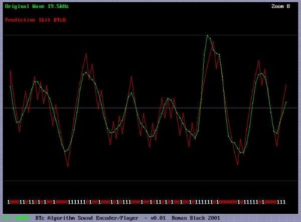
music. This is the BTc8 1bit algorithm on a 19.5kHz
sound. 19.5kHz = 20MHz PIC interrupted every 256
instructions. The RED wave is the encoded waveform,
as you can see it is a decent reproduction of the
original sound waveform (green). The "spiky" points
of the wave are not really important as they will be
filtered by the speaker inductance, or a simple
post-filter if needed. The main thing is that the
AVERAGE of the wave is a decent reproduction of the
original, as that is how your ear will hear it. :o)

You can still see the non-linearity in the encoded
waveform, look anywhere there are a few 1s or 0s
in a sequence. However this does not matter as the
encoding process allows for all errors and still
produces an acceptable reproduction waveform.


For more detail: Record+play fast 1bit sound on a PIC!

Current Project / Post can also be found using:

  • audio interface circuit pic16f877

The post Record+play fast 1bit sound on a PIC! appeared first on PIC Microcontroller.
Soundtrack using PIC16F688 Microcontroller

$
0
0

This project uses a microcontroller to
drive a speaker and play one of two
songs: Yakety Sax (the chase song
from the Benny Hill Show) and
Entrance of the Gladiators (the clown
juggling unicycle song).

Soundtrack

The tunes are stored as a series of
distinct notes.  The frequency and
duration of each a note is sent to a
function.  A square wave is generated
based on the inputs.  The nice thing
about this is it can be configured to
play any song you have the sheet
music to.


For more detail: Soundtrack using PIC16F688 Microcontroller

The post Soundtrack using PIC16F688 Microcontroller appeared first on PIC Microcontroller.
MIDI Chord Button Keyboard Using PIC18F4620 part 3

$
0
0

Connections
The following table documents the connecting leads and molex pin-header numbers tying the various interfaces together.

Header Pin no. Signal/Function Direction Header Pin no. Signal/Function
Chord Controller-SV1 1 RD7 ——> Matrix Decoder-SV4 1 Chord Sel. C
Chord Controller-SV1 2 RD6 ——> Matrix Decoder-SV4 2 Chord Sel. B
Chord Controller-SV1 3 RD5 ——> Matrix Decoder-SV4 3 Chord Sel. A
Chord Controller-SV1 4 RD4 ——> Matrix Decoder-SV4 4 Note Sel. E
Chord Controller-SV2 1 RD3 ——> Matrix Decoder-SV1 1 Note Sel. D
Chord Controller-SV2 2 RD2 ——> Matrix Decoder-SV1 2 Note Sel. C
Chord Controller-SV2 3 RD1 ——> Matrix Decoder-SV1 3 Note Sel. B
Chord Controller-SV2 4 RD0 ——> Matrix Decoder-SV1 4 Note Sel. A
Chord Controller-SV4 1 +5v ——> Matrix Decoder-SV7 1 +5v
Chord Controller-SV4 2 N/C Matrix Decoder-SV7 3 W (KEYDOWN)
Chord Controller-SV4 3 RB1 <—— Matrix Decoder-SV7 2 Y (/KEYDOWN)
Chord Controller-SV4 4 GND ——> Matrix Decoder-SV7 4 GND
Chord Controller-SV3 1 RC2 <—— Keypad-X1 6 In S3, 7, 11, 15
Chord Controller-SV3 2 RC1 <—— Keypad-X1 7 In S2, 6, 10, 14
Chord Controller-SV3 3 RC0 <—— Keypad-X1 8 In S1, 5, 9, 13
Chord Controller-SV3 4 RE2 <—— Keypad-X1 5 In S4, 8, 12, 16
Chord Controller-SV8 3 RB4 ——> Keypad-X1 1 Out S13-S16
Chord Controller-SV8 4 RB5 ——> Keypad-X1 2 Out S9-S12
Chord Controller-SV8 5 RB6 ——> Keypad-X1 3 Out S5-S8
Chord Controller-SV8 6 RB7 ——> Keypad-X1 4 Out S1-S4
Chord Controller-X3 1 /MCLR <—— Keypad-X2 1 RESET
Chord Controller-SV6 1 RC3 ——> Keypad-X2 2 LED1
Chord Controller-SV6 2 RC4 ——> Keypad-X2 3 LED2
Chord Controller-SV6 3 RC5 ——> Keypad-X2 4 LED3
Chord Controller-SV6 4 GND ——> Keypad-X2 5 GND
Chord Controller-SV6 5 +5v ——> Keypad-X2 6 +5v
Chord Controller-SV9 1 TX/RC6 (via 220R) ——> DIN SOCKET 5 MIDI-OUT
Chord Controller-SV9 2 GND ——> DIN SOCKET SCR Screen
Chord Controller-SV9 3 +5v (via 220R) ——> DIN SOCKET 4 MIDI-OUT
Chord Controller-SV10 1 +5v ——> Volume Pot LH Tag Top
Chord Controller-SV10 2 AN5 <—— Volume Pot Middle Tag Slider
Chord Controller-SV10 3 GND ——> Volume Pot RH Tag GND
Chord Controller-SV11 1 +5v ——> Pitch-wheel Pot LH Tag Top
Chord Controller-SV11 2 AN6 <—— Pitch-wheel Pot Middle Tag Slider
Chord Controller-SV11 3 GND ——> Pitch-wheel Pot RH Tag GND
Chord Controller-SV7 1 GND ——> FTDI-USB RS232-TTL 1 GND
Chord Controller-SV7 4 RX/RC7 <—— FTDI-USB RS232-TTL 4 (PC) TX
Chord Controller-SV7 5 TX/RC6 ——> FTDI-USB RS232-TTL 5 (PC) RX

Other connectors are documented on the schematic.
Note that I used a 10K Lin pot for the pitch wheel and 10K log for the volume pot. Although these values are a little on the high side for efficient analog conversion, in practise they work fine.

Chord Button Keyboard Shift Bar

I had originally intended to build the key matrix on a printed circuit board, and this would still be the preferred solution. Two thing deterred me. First, placement of the 6X6mm TACT switches on the PCB using the default outlines supplied in Eagle would have meant a longer keyboard than I wanted, and secondly, My Eagle license only allows Eurocard size boards – meaning there would be 3 boards to join together for the matrix. These two factors represented enough reason to look for another solution. I finally plumped for a single longish piece of matrix board. This allowed the key matrix to have the desired spacing – I fore-shortened the distance between each tag on the switches to 0.2 inches by straightening these close to the body of the switch, which then allowed a switch-to-switch pitch of 0.6 inches.
In solving one problem however, I created another. Mounting the finished board proved fiddly and difficult, and a solution using nylon nuts and bolts had to be adopted – you have been warned!
I terminated the matrix with 2 IDC headers – one 10-way and the other 20-way. Because my finished matrix was hand-wired, I haven’t given connection details for this, and you should refer to the matrix decoder schematic for connection details.
I’ve included a suggested matrix schematic in with the main Eagle project files, should you wish to augment this. A snapshot of this is given below:

Chord Shift Switch
I made provision for plugging in a foot-switch, but as the floor in front of me is rather busy when I’m playing, also provided a handy switch bar on the unit. It is crude but effective, and I’ll briefly describe it here.
A piece of 4mm (0.196 inch) diameter bright drawn mild steel was bent at 90deg each end so to form a bar 305mm (12 inch) long, with two short arms projecting roughly 40mm (~1.5inch) and 50mm. (2 inch) A thread was cut on each arm (I used M4), so that when the bar is placed through two locating holes on the front of the keyboard cabinet, and a washer and nut are threaded onto each arm, the shift bar is approximately 20mm from the keyboard cabinet front. (0.75inch)
Two small metal plates (I used Meccano) are fixed over the two holes on the cabinet front, and 2 collets (4mm) are fixed on each of the shift bar’s arms, which are then pushed into place in the cabinet.


For more detail: MIDI Chord Button Keyboard Using PIC18F4620 part 3

The post MIDI Chord Button Keyboard Using PIC18F4620 part 3 appeared first on PIC Microcontroller.
Treslie – A 3-phase speaker system for Leslie emulation using PIC18F26K20

$
0
0

This post describes the design and construction of a 3-phase loudspeaker intended for Leslie Speaker emulation. The unit is intended to be driven by a 3-channel audio amplifier The Brute, which in turn is controlled by LEMS, a micro-controller based control system, the construction of which both are described in companion posts.

3-phase speaker system

Companion posts are as follows:

Why Treslie?

Well, I once knew a girl with three heads.. No, you wouldn’t swallow that. But the name I’ve adopted is apparently quite common in the USA as a girl’s name. In fact it isn’t hard and you’ve probably already guessed that’s it’s a conflation of tres – meaning 3 (in spanish etc.) , and lie, the last part of Leslie. Whimsy? Probably, but I needed to call it something.

I’ve lifted a small part of text from the LEMS post which I hope clarifies what is being attempted, and this is given below:

I made the long sides ~12 inches (300mm), and the short sides ~6 inches (150mm). This gives an external angle of 120 degrees between the polar plane of each loudspeaker chassis. With an external height (on my cabinets) of around 27.5 inches (698mm), this gives a total volume of around 2.5 cu ft. Internal volume will be a little less than this, and of course each loudspeaker has only 1/3 of the volume, because of the 3 central partitions.

Each compartment should be made as airtight as possible – mainly due to the use of high-compliance (long-throw) loudspeaker units. These give good bass response in small cabinets, but require near-sealed enclosures, if damaging over-excursion of the loudspeaker cone is to be avoided. I found that screwed joints and the liberal use of a bathroom sealant that remains plastic when dry is the best solution. I advise against the use of glue. Access for maintenance would necessitate damaging a glued cabinet. With the sealant used, panels are easily disassembled, and the sealant can be simply replaced.

As this unit was intended to be experimental, and for use mainly at home with a small 70’s organ, and my guitars, I decided to cater for no more than about 30watts per channel, this keeps costs and size down, and allowed for the purchase of 3 reasonably-priced high-compliance units from my local stockist.
The loudspeakers are complimented with 3 cheap piezo horn units. Information on these suggested the use of series connected 47ohm resistors – I ignored this for the input powers I was using, and connected these up without the series resistor, to no ill effect.

Despite the loudspeaker units being cheap, it is worthwhile incorporating a suitable fuse in series. I used a 20mm, 1.6amp quick-blow item, that will protect the loudspeaker against gross DC flow. Too many loudspeaker designs omit this simple protection, with dire results in the case of accidents. The screw-in fuse-holders were sited on a small panel alongside the loudspeaker 4mm connector sockets.

Materials.
The sides were all made from reclaimed chipboard, mostly melamine-covered, of the type used for kitchen cabinet carcasses and cheap 70’s fitted wardrobes. The top and bottom were made from .. .. new chipboard, and the loudspeaker grilles from … new MDF.

Internal bracing was all new wood – mostly offcuts and scraps 3/4 X 3/4 inch (20mm X 20mm).

The sound absorbent material filling each speaker compartment has one important criteria – it should contain bubbles. Bubbles are just great at absorbing (converting to heat) the sound energy that would otherwise bounce around the hard reflective inner surfaces of the cabinet. Don’t let merchants sell you grossly over-priced ‘wadding’. My experiments have shown good results with: a) The remains of old hollow-fill pillows or cushions; b) Bubble-wrap; and c) Expanded polystyrene. All of these can be hoarded until needed – the latter two are usually used as packing materials for stuff delivered to your door.


For more detail: Treslie – A 3-phase speaker system for Leslie emulation using PIC18F26K20

The post Treslie – A 3-phase speaker system for Leslie emulation using PIC18F26K20 appeared first on PIC Microcontroller.
Project Ryu Lagger – Guitar Effect

$
0
0

Do you remember BOSS Slow Gear pedal? If your a guitarist you most likely do or at least you’ve heard of it. It was a great pedal sold from 1979 to 1982 and it was made in Japan. The pedal would cut the attack of your notes giving a swelling sound. It god famous for making the guitar sound kinda like a violin.

I always liked that effect and i even made a clone a few years back. It is based on a 2SK30 JFET and it was a pain getting these transistors. It was a lot of fun though and i though i should make a Project Ryu swell effect pedal and so LAGGER was born!

Project Ryu Lagger – Guitar EffectRecently i worked on a few projects with LM13600/LM13700, one of them is a nice noise gate / compressor unit which i will present at a later date, and i really like the VCAs that can be built with these chips.

To cut the attack of a note and then swell the volume basically we need a triggered fade in effect. This means that we need to control our VCA with a rising voltage using what i call a ramp generator.

In a previous article (Monitoring Amplifier モニターアンプ P3: Speaker Coupling Delay)   i described the circuit of such a ramp generator and it even has a command input. I will use this circuit with the LM13600 VCA all controlled digitally with a PIC18f1320.

The input is fed into an ADC channel to be rectified and averaged in order to detect when a note is played. Once it is detected, the ramp generator is triggered and provides the control voltage for the first VCA.

Project Ryu Lagger – Guitar Effect SchematicLM13600/LM13700 is a dual amplifier the second one is configured as a VCA with manually set control voltage. In the picture below you can see how the circuit works. The top signal is the input signal, the middle signal is the output of the ramp generator and the bottom signal is the trigger.

There is a problem with using the ramp generator circuit this way. The capacitor is discharged too quickly when the trigger is interrupted and this causes an audible thump noise when trigger goes off. Looking below at the schematic we can see the discharge current goes through CE junction of Q1.


For more detail: Project Ryu Lagger – Guitar Effect

The post Project Ryu Lagger – Guitar Effect appeared first on PIC Microcontroller.
SD/SDHC CARD SOUND RECORDER

$
0
0

Updated on 30.6.2015
The PIC16F876A’s ADC
digitizes the sound and store it in the SD or SDHC card. The firmware works for SD or SDHC cards only, for old SD (before 2009) use ver1 firmware. Do not use SDXC cards with this project because some of them work on 1.8V drive. The code detects whether the card is SD or SDHC and selects the proper addressing system for the card.
The PIC’s CCP is used as a DAC to convert the digital data back to audio. The sound is converted to 20KHz 8 bits mono in a format similar to .wav files. The quality of the audio is reasonable.
SD card interface the PIC in SPI mode. Reading and writing data is in multi-blocks. Memory is used at the rate of 20KB/s. The Error LED indicates error sent by the SD card. The software doesn’t use any file system, it just uses absolute memory addresses (raw). Since the programme is less than 680 bytes there is much resources left for adding features.SD SDHC CARD SOUND RECORDER
Audio input is 1Vp-p , you can use the mic circuit or other source. The CCP in PWM mode gives 20KHz wave with duty cycle modulated to the audio amplitude. A low pass filter removes the 20KHz component. I added a simple 2 transistors amplifier to boost the power to drive 32 Ohm speaker or headphones

  • SD/SDHC CARD FAT32 WAV PLAYER

This project is for .wav file type player (no recording). The software has the functions needed to read SD/SDHC card formatted in FAT32. The software can play only PCM 22.050KHz, 8 bits, mono. The bytes from the file are streamed to CCP1 (PWM mode) and with an external low pass filter you get the audio. The sound quality is OK for speech or medium quality music.
The software searches for files entries in the root directory only, it streams any file type without reading its name or type.
The circuit diagram is the same as the SD Sound Recorder minus the components for recording. Drawing is included with the software zip.
TO SET UP THE CARD:
Format the card with FAT32.
Create sound files type .wav
Name the files with short names, 8 low case characters max.
Save the files as 22.050KHz, 8 bits, mono.
Add the files to the root directory of the card (don’t use a subdirectory)

  • SD/SDHC CARD SOUND RECORDER 3.3V PIC16F690

This sound recorder has the same characteristics as the sound recorder with PIC16F876A. The difference is the supply voltage is 3.3V. This makes the direct drive of the SD card simpler. It also makes it easier to power it from a battery.
8MHz internal oscillator is used, if the frequency drifts it causes the playback to change speed. I left pins 2 and 3 free in case I have to use crystal oscillator.
The programming of the pic can be with 3.3V, if you have a pic programmer for 5V only remove the SD card while 5V is connected to the circuit, 5V will damage the SD card.

  • SD/SDHC CARD FAT32 WAVE PLAYER 3.3V PIC16F690

This wave player has the same characteristics as the wave player with PIC16F876A. The difference is the supply voltage is 3.3V. This makes the direct drive of the SD card simpler. It also makes it easier to power it from a battery.SD SDHC CARD SOUND RECORDER schematic
The playback speed can be changed by changing the time of TMR0 in the code.
The programming of the pic can be with 3.3V, if you have a pic programmer for 5V only remove the SD card while 5V is connected to the circuit, 5V will damage the SD card.

Troubleshooting: If the Error LED is on immediately on power up it means that the card failed to initialize. This code works for SD card rev 2 or SDHC card, it doesn’t work for SDXC (1.8V) or MMC or SD rev 1 cards. If your card is SD rev 1 you can use my firmware ver 1.
I’ve tested my code on 3 cards only and it may not work for all the cards, try using another make of card.

For more detail: SD/SDHC CARD SOUND RECORDER

Current Project / Post can also be found using:

  • internal circuit diagram of pic16f690
  • phone line recorder with microcontroller
  • sd card player circuit

The post SD/SDHC CARD SOUND RECORDER appeared first on PIC Microcontroller.

Bluetooth-Controlled Guitar FX Amplifier

$
0
0

As part of our final project for ECE 4760: Digital Systems Design Using Microcontrollers, we built a guitar amplifier with remote distortion and digital effects capabilities controlled from a smartphone via bluetooth.

Musicians often need to modify the configuration of their amplifiers when performing in concerts. This job is generally delegated to “roadies” who walk on-stage between sets to make adjustments. By building on top of generic amplifier circuitry we’ve been able to increase the capabilities of the standard guitar amp to allow remote control over all aspects of the amplifier’s sound.

Bluetooth-Controlled Guitar FX Amplifier

High-Level Design

Things I Can Do
  • Interface via bluetooth with smartphone
  • Perform Digital Effects
  • Modify bass, treble, and mid with physical knobs
  • Modify bass, treble, and mid digitally


There are two methods of interfacing with the amplifier. The first resembles a classic guitar amplifier where the user controls the analog effects via knobs connected to analog potentiometers. As is standard, the input of the amplifier comes from a ¼” TS Male Auxiliary cord attached to an electric or acoustic guitar. We have a ¼” TS female to 3.5 mm TRS male adaptor. This in turn connects to a 3.5 mm adaptor which is wired directly into our circuit.
The second style of interfacing with the amplifier is via the PIC32 microcontroller which controls and applies digital effects. These sound effects are outputs of a Belton BTSE-16 chip, which, through onboard DSP, synthesize various effects. These effects include chorus, flanger, phaser, tremolo, delay, reverb, and various combinations thereof.

As part of our ‘stretch goal’, the primary standard to which we’ve conformed is determined by the Bluetooth Special Interest Group (SIG). The standard for Bluetooth that we will be following is set by IEEE 802.15.1. The standard essentially sets the MAC addresses available for our use as well as limits our applications to the 2.4-2.485 GHz ISM band.

Analog Circuitry

A large portion of the project was devoted to building and testing standard analog circuitry for generating our desired effects. The schematics for these are included below.

Distortion

Our input goes through a common emitter amplifier with the 10k and 100k resistors deciding the gain of the circuit. The 100 nF and 10 uF capacitors decide the frequency response of the circuit with a lower input capacitance creating a more treble-heavy sound and a higher input capacitance creating a more bass-heavy sound. The schottky diodes act as clipping diodes creating the distorted sound we hear at the output.

Tone Stack

Our input goes through a high pass filter into a unity gain op amp (pins 1,2, and 3). The treble potentiometer adjusts a high-pass filter that sets the cutoff frequency below which no frequencies can pass. The bass potentiometer adjusts a low-pass filter that sets the cutoff frequency above which no frequencies can pass. The mid potentiometer acts as a band-pass filter that amplifies the center frequency about which treble and bass act. The level potentiometer changes the magnitude of the output signal by altering the gain of the second op-amp (pins 5, 6, and 7). Pins 4 and 8 are the ground and Vdd (8.84 Volts) of the op-amp respectively.This schematic was found on Run Off Groove. We modified the circuit to use LF353 op amps, as they gave the desired performance and were readily available.

Class-D Amplifier

We used a TPA3122D2 15 Watt Class-D power amplifier in order to drive the signal to our speakers. The class-D amplifier uses pulse width modulation to take our analog input signal, convert it into pulses, and amplify the signal. In order to set the voltage high enough to drive the speaker, a capacitor is placed between the FET-driven output and the bootstrap pin. The amplified pulse train is converted back into an analog signal with the passive low-pass filter (capacitor and inductor) out of the ROUT pins of the chip (pins 12 and 13). This low-pass filter acts as an integrator to the PWM. Finally, we add DC offset to our signal with our 470 uF capacitor in order to output a audible signal to our speakers, without negative output.

Digital Circuitry and Microcontroller Integration

An even greater portion of the project was dedicated to digital design and microcontroller programming…

Digital Effects Chip

The BTSE-16FX effect board provides 16 different digital audio effects when integrated into the amp. On the highest level, the chip takes in an input signal (sound wave), a 4-bit binary select signal, and outputs an affected signal. The schematic shown to the left demonstrates one way to set up the chip which involves stepping down a voltage to power the chip, filtering an input signal, and filtering the output signal. We modified this schematic by replacing the input voltage circuit with a simple 5-volt power supply, replacing the input filtering with a simple high-pass filter, and removing the output circuit entirely by operating directly on the output of the chip.

The 4-bit binary select signal for choosing an effect was generated directly off the Pic32. A user would make a choice for effect via his or her smartphone, and the resulting bluetooth signal is read via uart and translated to a 4-bit logic output.

HC-05 Bluetooth Module

The HC-05 bluetooth module handles almost all responsibilities associated with establishing a bluetooth connection with any other bluetooth-enabled device. The HC-05 communicates over UART with the PIC which both transmits and received data. The chip works by publishing a bluetooth service and allowing another client – the smartphone – to pair with the module. Through the use of a bluetooth terminal on a smartphone (eg. blu-term) one can send data and test the uart connection with the PIC.

Read More:   Bluetooth-Controlled Guitar FX Amplifier

The post Bluetooth-Controlled Guitar FX Amplifier appeared first on PIC Microcontroller.


MIDI Chord Button Keyboard Using PIC18f4620 part 1

$
0
0

Every time I sit down to document one of my projects, I try to remember the occasions in the past when looking at the finished web page, I might say ‘Well, I won’t do that again!’, because despite how many drafts I’ve gone through, there is always some aspect of the presentation that fails to measure up to my expectations. Then there’s the question of boredom. I don’t want all my project pages to look exactly alike, just reasonably easy to look at and above all else accurate. Finally, there is the thorny issue of the media itself. Most will realise that these pages are formed using WordPress php code, with a few (very few!) additional pieces of my own php. Presentation using combinations of tables, pictures and lots of text hits size problems which I don’t understand, and moreover, I’m unwilling to spend hours, even days trying to fix, so that there is a finite limit to some post lengths. Rather than pushing the boundaries, and risk the non-presentation of a post, I intend keeping each article instalment reasonably small in future. This will also cut down the loading time from the http://joebrown.org.uk/wp root, which several users have noted has grown a little too long lately!

Hexpad and processor board

The article presented here documents an update of my MIDI Chord Button unit described originally on connectable.org.uk. That article used a 28 pin PIC and was written in PIC assembly language. The unit is still in use, and I decided to build a bigger, hopefully better unit, and write the code in ‘C’.

The unit supports a button matrix of (up to) 20 columns, by 8 rows. Each column is a particular musical key e.g. Ab, and each row a chord type, e.g. Maj7th. A momentary-action shift key provides for a further 8 chord types.

The basic mechanism for scanning the matrix is essentially the same as in the original article, and I don’t want to repeat work, simply for the sake of it. Those of you contemplating basing your own project on the following are urged to read the original article.

For the uninitiated, the 20 key columns are arranged in a virtual ‘circle of fifths’. Which means that if you learn a chord sequence, you can transpose up or down the keyboard and play the same sequence again in a different key. This is very similar to the stradella layout of some Italian chord button accordians, and makes a lot of sense, being relatively easy to play.

There is a table of the columns and keys in the original article, but I’ve provided a sample set of panels for the matrix, so make no excuses for showing the new layout here.

I’ve drawn the unshifted chords available on the LH side of the buttons and the shifted chords available on the RH side of the buttons, this has been repeated at each 4th multiple of the columns only, so as to reduce eye strain!

The small table below shows the layout in schematic form, with the base note value for each key/chord combination (given in hex). Note that the keys marked with the suffix ‘1′ represent an octave key – i.e. a musical key that is also further down the keyboard. Also note that I’ve followed the convention of the accordian and renamed the octave keys for Db as C#, Bb as A# etc. If you are confused, look at the base note values given, these will show the relationships.

Perhaps the best thing about a home-built instrument is that you can mash it up to do exactly what you want, and not what some manufacturer (or people like myself) think you want.


For more detail: MIDI Chord Button Keyboard Using PIC18f4620 part 1

The post MIDI Chord Button Keyboard Using PIC18f4620 part 1 appeared first on PIC Microcontroller.

MIDI Chord Button Keyboard Using PIC18F4620 part 2

$
0
0

How chords are formed
Before discussing the processor board and software, it is worth mentioning how the chords are composed. I have provided the table below which shows the installed chords together with the intervals/notes they are constructed from, and examples of each in the key of C major.
Since the source-code is provided, and heavily commented, you can experiment, both with the actual chords installed, their placement on the matrix, and whether they will belong to the default or shifted group.
It is also likely that you may want to ‘open’ out some of the Phat Chords. I have left these in their minimum span configuration.
Slash Chords are not catered for on this unit, but a separate pedal-board is being developed which could be used to provide this facility.

Pitch Wheel inside

Chord Controller Board

The chords are produced by scanning a matrix of switches to produce a unique value for each chord comprising the key value of the chord (eg. C#) and the chord value (e.g. min7). The switch matrix is scanned by the matrix decoder board, (see part 1: MIDI Chord Button Keyboard Using PIC Microcontroller) and when a switch close is detected, a TTL ‘low’ is placed on connector SV7 which is connected to RB1 of the PIC Microcontroller on the Controller board, the schematic of which is shown below.
Note that this controller is dual-purpose. For the chord-controller, IC2 – the CD4073 is not required, and it should not be installed.
On the right, SV1 and SV2 carry the address lines to the matrix decoder, Power is also supplied to the matrix encoder board via SV4. The MIDI OUT signals are provided on SV9, whilst the command hexpad, RESET, and LED connections are via X3,SV3, SV6 and SV8.
Both pitch wheel and velocity/volume control are provided for, and these interface to SV10 and SV11. A connector pin on SV8 allows for the connection of a chord-shift switch.
Note that the Analog channels AN0-AN5, and the digital pins associated with these are not used in the design, but code is installed to read each of the analog signals and may be used to provide extra controller interfaces if desired.

Mapping Commands
As an example of how I mapped my hexpad to control the unit (and the connected synth) I append a code-snippet here of the main interpreter.
First of all the hexpad keyvalue is translated from it’s raw scan value then processed. The digit keys 0-9 are passed on without further action except for designating the keytype as DECIMAL_VAL.
The left-hand-side and bottom-row peripheral keys (except for zero) are assigned specific functions/roles, and control passed to a relevant routine as required.
I will discuss various code routines later.


For more detail: MIDI Chord Button Keyboard Using PIC18F4620 part 2

Current Project / Post can also be found using:

  • voice microcontroller ic
  • audio remote control with pic microcontroller
  • code written in micro C to play music using pic16f877a
  • dac pic programming project

The post MIDI Chord Button Keyboard Using PIC18F4620 part 2 appeared first on PIC Microcontroller.

LM386 based stereo audio amplifier with digital volume control

$
0
0

Due to its simplicity (requires minimum external components) and high availability, LM386 is very popular among hobbyists for use in low-voltage audio amplification applications. Most of the time a potentiometer is used at the input side of LM386 to provide a volume control in the output speaker. The potentiometer does not control the gain of the amplifier itself, but it creates a voltage divider network at the input, which in fact controls the fraction of the audio signal that is fed to the amplifier. This project is about a stereo audio amplifier using two LM386 ICs with digital volume control for both left and right speakers. So, how would you control the volume digitally? You are right, by replacing the traditional electro-mechanical form of potentiometers with digital potentiometer chips. This project uses MAXIM’s DS1868 dual digital potentiometer chip and a PIC microcontroller to control the volume of a stereo output from two LM386 ICs.

LM386 based stereo audio amplifier with digital volume control

Stereo audio amplifier with digital volume control

Theory

Tons of resources can be found on the internet about LM386 and so I am not going to describe it in detail here. The LM386 IC has got 8 pins which require very few external components to work as a mono amplifier. The circuit below is taken from the datasheet and shows the external components required for constructing a mono-channel audio amplifier with LM386. An external 10K potentiometer at the input is used to control the volume of the output speaker. For a stereo audio amplifier, we need two of this circuit.

Schematic LM386 based stereo audio amplifier with digital volume control

LM386 audio amplifier circuit

The supply voltage range for LM386 is wide (4-18 V). It can be powered with a +9V PP3 battery. For digital volume control feature, we will replace the external 10K potentiometer at the input stage with a digital potentiometer chip. MAXIM’s DS1868 is a dual digital potentiometer chip. Each wiper terminal has 256 positions between the high and low end of the potentiometer. The wiper position is set by an 8-bit control value that is stored into the I/O register of DS1868. The communication with the host microcontroller is done through a 3-wire serial interface. Please read my previous post, ‘How to interface MAXIM’s DS1868 digital potentiometer with a PIC microcontroller‘ for further detail on DS1868.

For more detail: LM386 based stereo audio amplifier with digital volume control

Current Project / Post can also be found using:

  • pic 16f mp3 player diy
  • microcontroller audio projects
  • pic audio projects
  • pic program for sound system

The post LM386 based stereo audio amplifier with digital volume control appeared first on PIC Microcontroller.

Record+play fast 1bit sound on a PIC!

$
0
0

BTc “Binary Time constant” algorithm.

A system to record and/or play sound in a bitstream format using just one digital output pin.

This is a sound playback system for a PIC or any other
microcontroller. It uses a clever encoding system to
mathematically model the actual performance of the RC filter
when the signal is encoded. This allows playback of good
quality sound with the absolute minimum software and
hardware.
The RC filter modeling (encoding algorithm) has been
refined to be PIC friendly in binary math, giving the
ability to playback AND RECORD in real time even on
a PIC, even with high rates up to 150+ kbit/sec.

The playback hardware is:
1 PIC digital output pin
1 resistor
1 capacitor
This makes it suitable for adding to small and low-cost
products, providing speech or sound confirmation of
keypress, talking PICs, sound record/playback devices,
etc.

Record+play fast 1bit sound on a PIC!Playback theory:

With this system sound playback only requires an RC
filter, and speaker, earphone socket etc.

Sound playback is very simple and fast. Data is a
single stream of bits, at a constant rate. The PIC
only needs to output one bit, on one pin, at a regular
timed rate to make the sound or speech.
Sound can be added to an existing PIC project, if
one pin and a few instructions each interrupt are
available.

Of course a digital output driving a simple RC filter 
is a common system, used in a number of cheap
applications, but it has drawbacks due to the RC time
constant giving a non-linear waveform.

My BTc algorithm provides a simple fix, and is fast
enough that it can do real-time compensation during
encoding. The math modeling of my encoder maintains a
model of the RC filter with zero accumulated error. If
the bitrate is high enough this system will give
CD-quality audio, due to the PWM effect of the dithering
output, and the RC filter linearity problem is fully
pre-compensated by the math modeling in the encoder.
So the player doesn't need any math. :o)

Encoding theory:

Encoding the sound is the hard part. The stream
of bits must be chosen correctly so that the final
output waveform is as close as possible to the original
waveform.

But the actual output waveform depends on the electrical
characteristics of the RC filter, ohms, uF etc.
We can make the voltage on the RC filter rise by sending
a "1" bit, or fall by sending a "0" bit, but unfortunately
the voltage doesn't rise or fall by an equal amount for
each bit... A form of compensation is needed to make
the filter produce the correct waveform.
Encoding methods.
In order to make the final playback waveform the
closest reproduction of the original waveform I tried
some closed-loop encoding systems, starting with the
two most obvious types of encoding;

REACTIVE:
If sample is higher than math model make a 1 bit.
If sample is lower than math model make a 0 bit.

PREDICTIVE:
In math model, make both bits, "predicting" each
result. Then pick the bit that gives the output
closest to the desired sound sample.

Reactive is easier with only one model needing to 
be generated with each bit. Predictive works a lot
better with all the sound samples I tried. I only used
the predictive algorithm in my encoder program.
Actually, I did support the reactive algorithm too,
but deleted it later when it proved inferior.

The trick is getting a fast and accurate math model
generated, especially fast enough for high speed
bitstream recording/encoding on a PIC.

BTc Encoding Algorithm:

I haven't seen this BTc algorithm used or claimed by
anyone, it is basic encoding methodology, just done
in a clever way to make it very easy and fast on a PIC.

The use of "Binary Time constants" to make the filter
calculation easy is my idea, but as always some other
person may have thought of it before I did. I don't
read enough technical papers these days. :o)

Why BTc??

This was my solution to the problem of math modeling
the RC filter on a PIC, and allows high speed encoding.
To model the RC filter it requires using the "time
constant" or Tc=RC if you remember the math.

Tc=0.63208, and is not of much use to us when trying
to encode each bit in real time unless you have a
Pentium with floating point.

When I was testing different high speed encoding
solutions I came across a very simple idea. Instead of
calculating Tc as given and then doing more calcs to
reduce to a bit speed level suitable for encoding, I
could simply combine the whole lot if a specific Tc
could be assumed.

This allows ONE calculation, a simple binary division,
to do the entire RC math modelling!

If a SPECIFIC time constant is chosen, the TIME for
each bit matches the performance of the RC filter in
a very specific way, ie; the charge on C will rise by
exactly 1/4 or 1/8 or 1/16 during the time that it
takes for one bit! Magic.

Here are the binary time constants, which I have
provided for you;

BTc2  = 0.6931 x Tc   (voltage changes 1/2 each step) 
BTc4  = 0.2877 x Tc   (voltage changes 1/4 each step) 
BTc8  = 0.1393 x Tc   (changes 1/8th etc)                  
BTc16 = 0.0645 x Tc
BTc32 = 0.0317 x Tc
BTc64 = 0.0157 x Tc 

Real world example?
So if we choose the BTc8 system, we know that the
charge (voltage) on the C of our RC filter rises
or falls by 1/8th of the remaining voltage with every
bit in our playback bitstream.

To do this we just need to tune the RC filter values
to our required bitrate. Don't worry too much about
the math, at the bottom of this page I have provided
software that will display your sound wave, encode it
in the way you choose, and display the encoded "math
model" waveform so you can see the actual waveform
you will get on your RC filter. Then it will save the
bitstream as a data file or even as complete PIC code
with the sound data as RETLW table, ready to program
directly into a PIC chip and play the sound back.

The math stuff
Imagine a PIC with 16MHz crystal, giving 4,000,000
instructions/sec. Now using prescaler=0 the timer0
interrupt occurs at 15625 Hz. That is an ideal rate
for our sound playback on a PIC.

Bitrate: 15625 Hz
(We choose BTc8) = 0.1393

So BTc8 = 0.1393 @ 15625 Hz
Therefore Tc = 0.1393 x 15625
Tc = 2177 Hz
Tc = 1 / 2177 = 0.000459 seconds

Tc = RC
R = Tc / C
(let's assume 0.1uF for convenience)

R = 0.000459 / 0.0000001
R = 4595 ohms

Hope that doesn't look too scary, but what we have
done is found that for our desired bitrate at
15625Hz, we can use an RC filter of 4595 ohms and
0.1uF capacitor, and for every bit which occurs
at 15625Hz the voltage on our RC filter will rise
or fall by EXACTLY 1/8th.
Record+play fast 1bit sound on a PIC!Now we can encode in real time on a PIC, and the
main filter math is a couple of add/subtracts and
one divide by 8.

This means we only have to do a handful of very simple
calculations for each bit. We can do the entire
encoding process and produce the encoded bitstream in
real time on a PIC to be played back perfectly on any
other PIC with just a resistor and capacitor. How cool.

Below is an example showing the BTc8 algorithm
encoding a file which contains speech and background
music. This is the BTc8 1bit algorithm on a 19.5kHz
sound. 19.5kHz = 20MHz PIC interrupted every 256
instructions. The RED wave is the encoded waveform,
as you can see it is a decent reproduction of the
original sound waveform (green). The "spiky" points
of the wave are not really important as they will be
filtered by the speaker inductance, or a simple
post-filter if needed. The main thing is that the
AVERAGE of the wave is a decent reproduction of the
original, as that is how your ear will hear it. :o)

You can still see the non-linearity in the encoded
waveform, look anywhere there are a few 1s or 0s
in a sequence. However this does not matter as the
encoding process allows for all errors and still
produces an acceptable reproduction waveform.


For more detail: Record+play fast 1bit sound on a PIC!

Current Project / Post can also be found using:

  • audio interface circuit pic16f877

The post Record+play fast 1bit sound on a PIC! appeared first on PIC Microcontroller.

Soundtrack using PIC16F688 Microcontroller

$
0
0

This project uses a microcontroller to
drive a speaker and play one of two
songs: Yakety Sax (the chase song
from the Benny Hill Show) and
Entrance of the Gladiators (the clown
juggling unicycle song).

Soundtrack

The tunes are stored as a series of
distinct notes.  The frequency and
duration of each a note is sent to a
function.  A square wave is generated
based on the inputs.  The nice thing
about this is it can be configured to
play any song you have the sheet
music to.


For more detail: Soundtrack using PIC16F688 Microcontroller

The post Soundtrack using PIC16F688 Microcontroller appeared first on PIC Microcontroller.

Viewing all 110 articles
Browse latest View live


<script src="https://jsc.adskeeper.com/r/s/rssing.com.1596347.js" async> </script>